Płyta może wyglądać na czystą. Może przejść test ilościowego jonowego oznaczonego na zielono na certyfikacie. A mimo to może przeciekać w terenie.
To nie jest cynizm. To geometria, wilgotność i czas doganiają pomiar, który wyglądał w niewłaściwym miejscu.
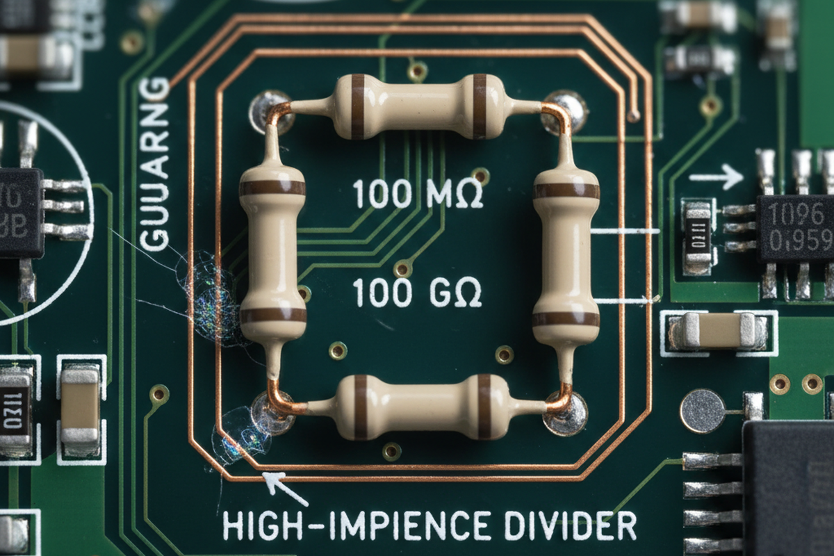
Rozważ znany wzór w przemysłowym czujnictwie: platforma z dzielnikiem wysokiej impedancji (100 MΩ do 1 GΩ) zachowuje się idealnie na stanowisku i przechodzi kontrole, ale zaczyna wykazywać odchylenia po wdrożeniu na wybrzeżu. Argument w pokoju jest zawsze ten sam: producent kontraktowy ma raport ROSE; spełnia limit; powinno być w porządku. Tymczasem jedynym ustawieniem, które ujawnia odchylenie, jest narażenie na wilgotność z biasem — pomyśl o 85%RH z nałożonym biasem na wrażliwą sieć — gdzie awaria pojawia się powoli, jak timer.
Gdy podzielisz awarię na konkretną okolicę (zwykle niskoprofilowy obszar LGA/QFN blisko pierścienia ochronnego), historia „czystej masy” rozpada się. Lokalna ekstrakcja wokół punktu gorącego ujawnia zanieczyszczenia, których cała liczba na płycie nigdy nie wychwyciła. Działania korygujące, które faktycznie przesuwają wskaźnik, nie są heroiczne. To zwykłe dyscypliny: trend rezystancji płukania, zasady ładowania zapobiegające zacienianiu, oraz dyscyplina lutowania reworku wymuszona przez rewizję instrukcji pracy powiązaną z ECO.
Tu zaczynają się mnożyć skróty: „Czy nie możemy po prostu nałożyć powłoki konformalnej?” „Czy nie możemy poprosić o czystszy certyfikat?” „Czy nie możemy zwiększyć odstępów?” Te pytania są pocieszające, bo brzmią jak zamknięcie sprawy. Nie są.
Certyfikat czystości to dane wejściowe. Nie jest dowodem na to, że powierzchnia o wysokiej impedancji lub wysokim napięciu pozostanie izolacyjna w wilgotności, przy biasie i starzeniu się.
Prawdziwy dowód wygląda inaczej: walidacja powiązana z mechanizmem, dopasowana do trybu awarii, plus kontrole procesu, które czynią wyniki czyszczenia powtarzalnymi — w tym części produkcji, które wszyscy chcieliby, żeby się nie liczyły, jak prace poprawkowe i selektywne poprawki lutownicze.
Co oznacza „Czyste”, gdy liczą się nanoampery
Dla zespołów o wysokiej impedancji i HV, „wystarczająco czyste” nie może oznaczać po prostu „wyodrębniliśmy jony z dużego obszaru i liczba ta była poniżej limitu”. Celem jest coś węższego i bardziej wymagającego: zapobieganie dryfowi wycieku i degradacji izolacji w różnych porach roku, profilach przechowywania i czasie pod napięciem. To cel związany z niezawodnością elektryczną, odmienny od standardów kosmetycznych. Cienka, łatająca się warstwa osadu, która nigdy nie wywoła alarmu podczas inspekcji wizualnej, może stać się elektrycznie aktywna w wilgoci. Gdy zostanie nałożone napięcie, przestaje być pasywnym zanieczyszczeniem i staje się częścią ścieżki przewodzenia.
Mechanicznie, składniki są proste: resztki jonowe, wilgotność, bias, czas i geometria, która pozwala na mostek filmowy tam, gdzie diagramy odstępów zakładały powietrze. Trudność polega na tym, że geometria, na której Ci zależy, jest często ukryta. Strefy podkomponentowe — QFN, LGA, BGA, piny o gęstym rozstawie i krawędzie klejów lub mocowań — to miejsca, gdzie resztki są uwięzione i gdzie zasięg mycia jest najgorszy. To także dokładnie te miejsca, które zespoły nie mogą dobrze inspekcjonować, i dokładnie tam test ekstrakcji masowej zniekształca problem. Jeśli ktoś zapyta: „Jak czyścić pod QFN/LGA?”, nie zadaje pytania początkującego. Pyta o sedno, czy historia czyszczenia jest prawdziwa, czy tylko teatrem.
Praktycznie, walidacja musi być lokalizowana wokół wrażliwego węzła. Pierścień ochronny wokół wejścia elektrometru, wysokiej wartości dzielnik lub obszar z wysokim napięciem to nie „tylko kolejny obszar płyty”. To gorący punkt z inną fizyką awarii. Ścieżka wycieku często podąża za zwykłymi cechami: krawędziami maski lutowniczej, okolicami via-in-pad lub obwodem niskiego odstępu, gdzie resztki fluxu są uwięzione i aktywowane przez wilgoć. Dlatego „zwiększanie odstępów” rzadko rozwiązuje niezawodność HV na montażu, który nadal ma resztki: filmy powierzchniowe nie respektują nominalnych odstępów narysowanych w CAD.
Shiny nie jest miarą.
Niekomfortowa prawda jest taka, że wiele programów weryfikuje czyszczenie tak, jakby zanieczyszczenie było jednolite i widoczne. Uszkodzenia wysokiego impedancji i HV zazwyczaj nimi nie są.
Mechanizm śledzenia: Resztki → Wilgotność → Bias → Wycieki (i jak to udowodnić)
Plan walidacji zaczyna się od stwierdzenia mechanizmu awarii w jednym zdaniu. W tym przypadku zwykle jest to przewodzenie powierzchniowe i dryf (czasami postępujący w kierunku migracji elektrochemicznej), a nie natychmiastowe uszkodzenie. Następnie plan wymienia konieczne warunki: resztki jonowe gdzieś na powierzchni lub uwięzione pod obudową, wilgotność wystarczająca do stworzenia przewodzącej warstwy, nałożone pole elektryczne przez region (bias) oraz wystarczająco czasu, aby wyciek ustabilizował się w „nowej normalnej”. Ten czas jest często niedoceniany przez zespoły; testy laboratoryjne są krótkie, podczas gdy ekspozycja w terenie trwa długo.
Gdy ta przyczynowa sekwencja zostanie nazwana, plan mapuje, gdzie każdy składnik ukrywa się na zmontowanym urządzeniu. Pod niskim odstępem LGA/QFN blisko dzielnika 100 MΩ znajduje się klasyczna pułapka: region jest elektrycznie wrażliwy, fizycznie trudny do umycia i łatwy do skażenia podczas przeróbek. Gdy program zauważa skupienie dryfu po wdrożeniu na wybrzeżu lub magazynowaniu latem, rzadko oznacza to, że płyta stała się „brudniejsza” w dramatyczny sposób. Oznacza to, że środowisko w końcu dostarczyło wilgoci potrzebnej do zamknięcia obwodu przez warstwę resztkową, która już tam była, a bias uczynił ścieżkę wycieku spójną.
Wilgotność z biasem nie jest w tym kontekście wymyślnym testem; to sposób na odtworzenie rzeczywistych składników awarii w terenie. Ma ona standard fałszywego fałszerstwa: jeśli wilgotność z biasem na odpowiednim poziomie stresu nie zmienia rezystancji izolacji w czasie w regionie hotspot, hipoteza o resztkach traci na sile.
To także miejsce, gdzie powinna być rozwiązana konfuzja „ROSE pass = bezpieczne?”. Testy jonowe w masie mogą być przydatnymi ekranami, ale nie gwarantują, że jeden centymetr kwadratowy pod obudową z niskim odstępem blisko pierścienia ochronnego jest czysty. Rzadko odzwierciedlają one warunki pracy — chemia ekstrakcji, lokalizacja próbek i wrażliwość na zlokalizowane resztki mają znaczenie. Raport może być „prawdziwy”, a mimo to nieistotny dla mechanizmu awarii. Pytanie o walidację nie brzmi „Czy spełnił numer?”, lecz „Czy ta zmontowana jednostka utrzymuje zachowanie izolacji pod wilgotnością i biasem przez czasy, które produkt faktycznie będzie widział?”
Nie istnieje uniwersalny próg „akceptowalnych resztek”, który można uczciwie przypisać wszystkim wysokiego impedancji/HV projektom. Akceptowalny poziom zależy od skali impedancji (nanoampery nie są mikroamperami), gradientów napięcia, geometrii i środowiska. Sposobem na zarządzanie tą niepewnością jest korelacja, a nie pewność. Wybierz reprezentatywną strategię płyty lub próbki, zastosuj profil wilgotności z biasem, który obejmuje prawdopodobne warunki w terenie (85°C/85%RH to popularny zakres, ale nie jedyny), i skoreluj lokalne wskaźniki skażenia (lokalna ekstrakcja wokół regionu hotspot, testy SIR/ECM, rezystancja izolacji vs. czas) z elektryczną wydajnością, na której Ci zależy.
Główna zasada jest prosta: jeśli awaria obejmuje wilgotność + bias + czas, walidacja musi obejmować wilgotność + bias + czas, w odpowiednim miejscu.
Minimalny pakiet walidacyjny (Co udowadnia, czego nie)
„Minimalny pakiet walidacyjny” nie jest rozwodnioną wersją idealnego programu. To celowa kompromis: wystarczająco, aby wykluczyć najczęstsze fałszywe pętle zaufania, nie zamieniając projektu w niekończący się wysiłek naukowy. Przestaje traktować certyfikat jako linię mety. Zamiast dodawać testy dla samego testowania, ten pakiet reprezentuje najmniejszy zestaw kontroli i dowodów, które znacząco zmniejszają prawdopodobieństwo powrotu dryfu/wycieku.
Co najmniej, program musi mieć dwie kategorie: (1) dowody przesiewowe/procesowe, że czyszczenie jest kontrolowane i powtarzalne, oraz (2) co najmniej jeden test elektryczny powiązany z mechanizmem skupiającym się na hotspot.
Po stronie procesu, program powinien wymagać odczytów audytowalnych z linii czyszczenia i CM, a nie marketingowych oświadczeń. Spójne programy mają określone cechy: udokumentowaną recepturę mycia, zapisy konserwacji obejmujące inspekcję/czyszczenie dysz na myjce wodnej z pryskami, oraz metodę załadunku unikającą cieniowania (zasady odstępów koszyków, które są faktycznie przestrzegane, a nie tylko przyklejone do drzwi).
Jakość płukania zasługuje na nadmierną uwagę, ponieważ łatwo ją zaniedbać i zmienia wyniki. Rejestrowanie rezystancji płukania DI, które trenduje w czasie, jest bardziej informatywne niż dyskusje o „silniejszej” chemii, podczas gdy jakość wody płukania się waha. To także miejsce, gdzie należy uwzględnić kompatybilność materiałów — obudowy złączy, etykiety, silikony/underfille, uszczelki. Zamiana chemii, która powoduje zamglenie plastiku lub spuchnięcie uszczelki, może „rozwiązać” skażenie, ale stworzyć inny problem z niezawodnością. Podstawowa kontrola próbki plus przegląd danych technicznych/SDS jest obowiązkowa, gdy w grę wchodzą zamienniki.
Po stronie mechanizmu, wybierz jeden test przypominający składniki awarii i jedno pomiar, które celuje w hotspot. Może to być wilgotność z biasem z określonym biasem w wrażliwym regionie (odstęp HV lub obszar dzielnika wysokiej wartości) połączona z trendem rezystancji izolacji vs. czas, lub test SIR/ECM ukierunkowany na proces i użyte materiały. Połącz to z lokalną ekstrakcją wokół regionu wysokiego ryzyka (sąsiedztwo pierścienia ochronnego, pod obudowami z niskim odstępem) zamiast średniej dla całej płyty. Chodzi o to, aby program był wrażliwy na sposób, w jaki te awarie faktycznie występują: zlokalizowane, aktywowane przez wilgotność, stabilizowane przez bias i ujawniane w czasie.
Zakupy i wczesne rozwiązywanie problemów często zaczynają od błędnego pytania: „Który czyścik powinniśmy kupić?” Jeśli wyniki czyszczenia zmieniają się, gdy płyty są układane w koszyku lub gdy dysze są odblokowane, zespół nie ma problemu z chemią. Ma problem z możliwością procesu. Wybór chemii ma znaczenie — szczególnie w przypadku typów fluxów i ograniczeń materiałowych — ale jest to ostatnia regulacja, którą należy wykonać po widocznych i kontrolowanych mechanikach, załadunku, jakości płukania i monitorowaniu.
I nie: powłoka konformalna nie jest planem czyszczenia. Powłoka może zmniejszyć ryzyko lub zamknąć resztki w zmontowanym urządzeniu i zamienić je w źródła długoterminowego dryfu. Jeśli używa się powłoki, musi mieć własne kontrole procesu (strategia maskowania, pomiary grubości logowane na partii, weryfikacja utwardzenia i plan przeróbek) i nadal nie można traktować tego jako pozwolenia na pomijanie walidacji czystości hotspot.
Przeróbka i selektywne lutowanie: Ślepy punkt walidacji
Jeśli plan walidacji pomija ponowne prace, to zatwierdza fikcyjny proces produkcyjny.
Budowa pilotażowa może przejść ICT i wyglądać na stabilną, a następnie rozwinąć przerywane awarie wysokiej impedancji po dniu w komorze wilgotności z zastosowanym napięciem. Analiza po fakcie często ujawnia coś bolesnie zwyczajnego: dwóch techników wykonujących „takie samo” poprawki używało różnych fluxów i różnych nawyków czyszczenia. Jeden używał pióra fluxowego i wacika nasączonego IPA; inny używał innego fluxu i materiału do wycierania, który zostawiał włókna. Instrukcja pracy mówiąca „czyścić w razie potrzeby” to tylko życzenie. Gdy awarie są powiązane z notatkami MRB lub NCR, a następnie z stanowiskiem ponownej pracy, wzór przestaje wyglądać na losowy. Zaczyna wyglądać jak niekontrolowany drugi proces produkcyjny.
Dlatego rework i selektywne lutowanie muszą być w zakresie walidacji. Kontrole są wyraźne: zamknięta lista fluxów (numery części śledzone w szafce narzędziowej), zdefiniowane rozpuszczalniki i materiały do wycierania (bez „przepisów ludowych” zależnych od osoby), jasne zasady trasowania, kiedy płyty muszą wrócić do mycia po poprawkach, oraz kryteria weryfikacji dopasowane do mechanizmu awarii (nie tylko „wygląda na czyste”). Jeśli program musi przejść przez ECO i naprawy serwisowe w terenie, walidacja powinna obejmować co najmniej jeden cykl rework w macierzy testów dla regionu gorącego punktu, ponieważ tam są wprowadzane resztki late i cicho.
Istnieje również subtelna, ale ważna niepewność do zarządzania: etykieta fluxu z napisem „no‑clean” nie jest gwarancją fizyczną, a formulacje się różnią. Traktuj typ fluxu jako zmienną kontrolowaną. Gdy się zmienia, ponownie zweryfikuj zachowanie gorącego punktu pod wpływem wilgotności i napięcia. W przeciwnym razie program kończy się „zweryfikowany” dla fluxu, którego nie używa się podczas nieporządnych, presjonowanych czasowo poprawek, które faktycznie się zdarzają.
Objętość reworku może być mała, a mimo to dominować ryzyko, ponieważ wrażliwy węzeł jest zlokalizowany. Ryzyko jest proporcjonalne do tego, czy zdarzenie reworku dotknęło niewłaściwego centymetra kwadratowego, a nie do tego, ile płyt zostało poddanych reworkowi łącznie.
Red‑Teaming artefaktów komfortu (ROSE, CoCs, wizualne, Hipot)
Główny sposób myślenia jest prosty: osiągnij KPI czystości, przejdź test hipot, wyślij. Artefakty komfortu są ułożone jak tarcza: raport ROSE, certyfikat dostawcy CoC, inspekcja wizualna, może barwnik UV, i na końcu test hipot. Każdy artefakt mierzy coś rzeczywistego, ale żaden z nich sam w sobie nie mierzy „to zespawanie nie rozwinie przewodzenia powierzchniowego i dryfu przy wilgotności pod obciążeniem z upływem czasu”.
ROSE to gruba siatka wsadowa; nie jest zaprojektowana do mapowania lokalnych pozostałości pod obwodem QFN lub na krawędzi pierścienia ochronnego. Certyfikat dostawcy CoC opisuje materiał przychodzący, a nie stan zmontowanej płytki po reflow, selektywnym lutowaniu, obsłudze i przeróbkach. Inspekcja wizualna (nawet z pomocą UV) pomaga wykryć poważne pozostałości i problemy z jakością wykonania, ale cienkie, elektrycznie aktywne filmy mogą być niemal niewidoczne. Hipot potwierdza wytrzymałość w danym momencie w określonych warunkach; nie przewiduje automatycznie dryfu przewodzenia powierzchniowego przy 85%RH z obciążeniem przez godziny lub dni. To nie są krytyki testów. To przypomnienia o ich ograniczeniach.
Jeśli produkt dba o nanoampery, powinien je weryfikować za pomocą nanoamperów — lub testów, które je wiarygodnie przewidują.
Pragmatyczny przebudowa zachowuje artefakty komfortu jako ekrany, ale przestaje je używać jako zamknięcia. Dodaj jeden mechanizm‑powiązany test dowodowy w gorącym punkcie pod wilgotnością i obciążeniem na odpowiedni czas, i połącz go z pomiarem lokalnego zanieczyszczenia lub dowodami w stylu SIR/ECM. Ta pojedyncza zmiana często robi więcej, aby zapobiec dryfowi i zwrotom z pola, niż rozbudowa listy certyfikatów.
Jak określić zakres bez rozpoczynania projektu naukowego
Wiarygodny program nie próbuje w nieskończoność walidować „czystości” wszędzie. Skupia się na konsekwencjach i wiarygodności.
Zacznij od wrażliwego węzła i jego otoczenia: wysokiej wartości dzielniki (100 MΩ i więcej), wejścia elektrometru z pierścieniami ochronnymi oraz odstępy HV, gdzie powierzchniowe filmy mogą mostkować przeskórzenie. Następnie zdecyduj, jak wygląda świat produktu w różnych zakresach: łagodne warunki wewnętrzne, ekspozycja na wilgotność przybrzeżną lub gorące magazynowanie, a potem wilgoć podczas transportu i wdrożenia. Ta decyzja o zakresie wpływa na wybór testów stresowych. Informuje też o doborze próbek: lokalne pobranie wokół gorącego punktu jest bardziej informatywne niż średnie dla całej płytki, gdy przyczyną awarii jest zatrzymanie pod komponentem. Jeśli CM może pokazać trendy rezystywności płukania, logi konserwacji myjek i diagramy obciążenia, które zapobiegają zacienieniu rozpylania, zmniejsza to potrzebę powtarzalnych testów eksploracyjnych. Jeśli nie, program powinien zakładać zmienność, dopóki nie zostanie to udowodnione inaczej.
Ten przewodnik celowo unika klasyfikowania marek środków czyszczących, podawania kroków czyszczenia dla hobbystów czy omawiania historii klauzul norm. Ten materiał nie pomaga zespołom profesjonalnym zdecydować, czy wysokozimpedancyjna/ HV montaż pozostanie stabilny pod wpływem wilgotności i obciążenia. Zazwyczaj odciąga uwagę od kluczowych elementów: geometrii, zdolności procesu i mechanizmowo powiązanej walidacji.
Praktyczna gwiazda przewodnia jest prosta: przestań pytać, czy płytka jest „czysta” w abstrakcji. Zapytaj, czy gorący punkt pozostaje izolujący w warunkach wilgotności, obciążenia, czasu i rzeczywistego przeróbki — i wymuś pomiary, które mogą na to odpowiedzieć.