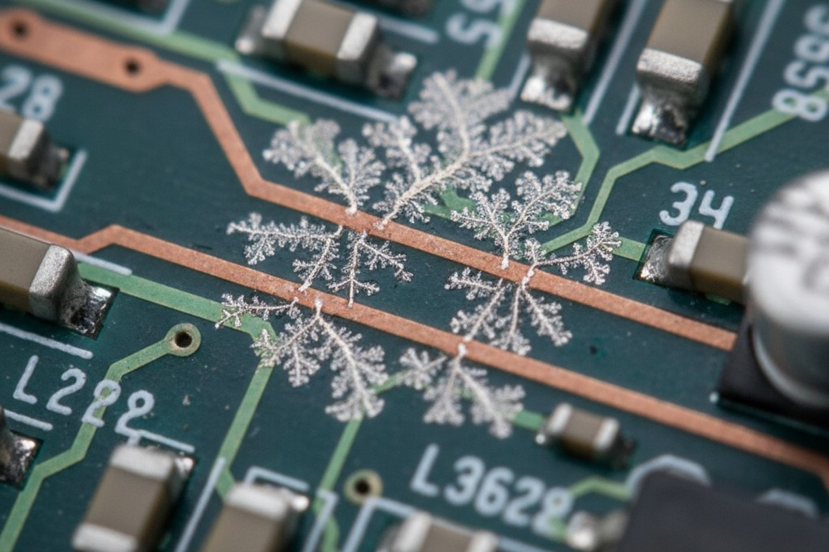
Industrial controllers returned from the field tell a familiar story. A conformal coating that appeared flawless during final inspection now hosts a web of conductive pathways after months in a damp environment. Dendritic growth spiders between traces. Corrosion blooms beneath what should have been a protective barrier. The common thread in these failures is not the coating itself, but what lies beneath: residues from no-clean flux, left behind before the coating was ever applied.

Pairing no-clean flux with acrylic or urethane conformal coatings creates a predictable failure mode in humid conditions. This isn’t a material defect or a sloppy application; it’s a consequence of fundamental chemistry. No-clean flux is designed to leave behind ionic residues. When sealed under a coating and exposed to moisture, these inert deposits become active electrochemical sites. Instead of protecting the assembly, the coating traps moisture against the contaminated surface, accelerating the very degradation it was meant to prevent.
Understanding this mechanism requires a close look at the behavior of flux residues and the properties of common coatings. At Bester PCBA, we’ve seen RMA rates for humidity-exposed assemblies drop by over 60 percent when manufacturers manage residue before coating. That process begins with a simple recognition: “no-clean” is a soldering classification, not a guarantee of coating compatibility.
The Invisible Failure Mechanism
The problem doesn’t announce itself during production. Freshly coated assemblies pass electrical tests with no anomalies in their insulation resistance. The coating looks uniform under magnification. Failure only emerges when the assembly is operating in its end-use environment, where temperature swings and ambient humidity activate the residues trapped beneath the surface.
Moisture finds its way in through the coating itself. Even the best conformal coatings are not absolute barriers to water vapor. Acrylics, popular for their ease of use, have moisture vapor transmission rates that allow water molecules to diffuse through the polymer matrix. Urethanes, prized for their toughness, are less permeable but still not hermetic. Over time, especially in environments with high humidity or thermal cycling, moisture inevitably reaches the interface between the coating and the PCB.
At that interface, the moisture encounters the flux residues. Composed of partially volatilized activators and rosin carriers, these residues are hygroscopic—they absorb water and form a localized electrolyte. With the assembly powered on, an electric field exists between adjacent conductors. The electrolyte provides a conductive medium for ions to migrate. Electrochemical reactions begin at the anode, dissolving metal from copper traces or lead finishes. At the cathode, these ions are reduced and deposited as metallic dendrites, which grow along the electric field lines until they bridge conductors, causing current leakage or an outright short.

The coating doesn’t prevent this; it makes it worse. By sealing the residue against the board, the coating stops moisture from evaporating during dry cycles. The contaminated zone stays wet far longer than it would on an uncoated assembly, allowing the electrochemical reactions to proceed continuously. A marginal reliability risk on a bare board becomes a near certainty under a coating that traps both the residue and the moisture it attracts.
Why Ionic Residues Concentrate Under Coatings
The trouble begins during reflow soldering. Flux has one job: remove oxides from metal surfaces so molten solder can form a proper bond. No-clean fluxes use weak organic acids, sometimes boosted with halide activators, to accomplish this. During reflow, these acids react with copper oxide and other contaminants, forming soluble metallic salts.
In a perfect reflow cycle, most of these reaction products and the flux vehicle itself would volatilize at peak temperatures of 240–250°C. What’s left behind is the residue, designed to be benign in typical operating conditions. It consists mainly of rosin or polymer film-formers, heavier organic acids, and trace amounts of ionic species.
The key word is trace. No-clean flux residues are not ion-free. They contain carboxylate anions from the organic acids, metal cations complexed with flux components, and—if used—halide ions. While the total ionic load is typically too low to cause problems on an uncoated board, it is not zero. Applying a conformal coating seals these trace ions in place, concentrating them at the board-coating interface.
The transformation from inert residue to active contaminant begins when moisture diffuses through the coating. Water molecules dissolve the ionic species, forming a thin electrolyte film between the coating and the board. This film may only be nanometers thick, but it’s enough. The electric field from powered traces drives ion migration. Copper at the anode dissolves into copper cations, which travel through the electrolyte to the cathode, where they deposit as metallic copper. This deposition isn’t uniform; it follows the path of highest field intensity, creating the branching, tree-like structures of dendrites. If halide ions are present, they accelerate the process by forming highly soluble copper-halide complexes.
On an uncoated board, this process would self-limit as the electrolyte dries out. Under a coating, the moisture is trapped. The electrolyte persists. As long as the board is powered and the humidity is high enough, the dendrites grow continuously until they bridge the gap between conductors and the assembly fails.
Material Vulnerabilities: Acrylic vs. Urethane
Not all coatings are equally susceptible. The interaction between flux residues and moisture depends heavily on the coating’s permeability, its adhesion to contaminated surfaces, and its response to environmental stress.
Acrylic coatings are thermoplastic polymers, valued for their ease of application and rework. They are also among the most permeable to moisture, with vapor transmission rates of 20 to 50 grams per square meter per day. This means moisture quickly finds its way to the PCB surface. Adhesion is their second vulnerability. Acrylics bond through mechanical interlocking and weak van der Waals forces, but flux residues create a contamination layer that prevents a strong bond. The coating may look fine initially, but thermal cycling or mechanical stress can cause it to delaminate. The resulting gap fills with a thicker, more conductive electrolyte layer, accelerating corrosion and dendrite growth.
Urethane coatings are rigid, thermosetting polymers that offer superior resistance to abrasion and moisture, with transmission rates of just 5 to 15 g/m²/day. While this helps, urethanes introduce a different failure mode. They have a high modulus of elasticity and a coefficient of thermal expansion that differs from the PCB substrate. Over a clean surface, a urethane coating can withstand the stress of thermal cycling. Over a layer of flux residue, however, adhesion is weak. Thermal stress can cause the rigid coating to crack or delaminate at this boundary. A crack provides a direct path for moisture to wick along the contaminated interface, bypassing the coating’s low permeability and creating concentrated zones of corrosion and dendritic growth.
Other materials behave differently. Silicone coatings are highly permeable but “breathe,” allowing moisture to escape as easily as it enters, which prevents accumulation at the interface. Parylene, applied as a vapor, creates an extremely thin, conformal, and low-permeability barrier, but its performance can be compromised by pinholes or the way it encapsulates residues. While neither is immune, their failure mechanisms are distinct from those of acrylics and urethanes.
The Clean-Before-Coat Decision

The solution is a process decision: when does the ionic contamination on a no-clean assembly become unacceptable for conformal coating? The answer depends on the flux, reflow profile, coating material, and service environment.
Quantifying contamination requires testing, as visual inspection is useless. A board can look clean while harboring enough ionic content to cause failure. The most common method is the Resistivity of Solvent Extract (ROSE) test, which measures the conductivity of a solvent used to wash the board. The result is expressed in sodium chloride equivalents per unit area (e.g., µg of NaCl/cm²). For more detailed diagnostics, ion chromatography can identify specific ionic species and their concentrations.
Acceptable contamination levels vary by coating. Based on field experience and accelerated testing, acrylic coatings over no-clean flux often fail in humid environments when ionic contamination exceeds 1.56 µg/cm² NaCl equivalent. Urethanes can tolerate slightly higher levels, around 2 to 3 µg/cm², due to their lower moisture permeability.
The decision to clean is driven by these thresholds. If a well-controlled process using a low-residue flux keeps contamination below the limit for the chosen coating, cleaning may be unnecessary. However, factors like an incomplete reflow profile, the use of high-activity halide fluxes, or complex board geometries that trap residues all argue for cleaning. When in doubt, or when the end environment involves high humidity, cleaning before coating is the only reliable path.
Designing to Eliminate Residue Traps
Prevention is better than remediation. Process design choices made long before coating can minimize the conditions that lead to failure.
Flux residues are not spread evenly. They pool under large components, get drawn into gaps between fine-pitch pins, and concentrate in corners where airflow during reflow is poor. These are the hot spots for ionic contamination. One approach is to mask these high-risk zones during coating. Another is selective coating, where only sensitive areas of the board are protected, leaving high-residue areas uncoated. This reduces the risk of trapping contaminants but requires careful analysis to ensure unprotected areas are not vulnerable.
Board layout also plays a critical role. Orienting large components to minimize flux shadowing and ensuring adequate spacing between parts can dramatically reduce residue concentration. These design-for-manufacturability choices have a direct impact on the long-term reliability of the coated assembly.
Post-Coat Inspection: Finding Problems Before They Ship

Even with rigorous process control, verification is essential. Post-coat inspection confirms proper application and hunts for signs of trapped contaminants.
Trapped residues often leave visual clues. A mottled or “orange-peel” texture can indicate poor wetting over a contaminated area. Bubbles, voids, or subtle color shifts can also signal poor adhesion. Automated Optical Inspection (AOI) systems, especially those using UV light with fluorescent coatings, are excellent at catching these defects.
But visual inspection can’t measure electrochemical risk. For that, electrical testing is required. A significant drop in insulation resistance between adjacent conductors after humidity exposure is a clear red flag. Surface Insulation Resistance (SIR) testing provides the most definitive data. By applying a bias voltage to a test pattern under controlled high-temperature, high-humidity conditions (typically 85°C/85% RH), SIR testing can simulate the field failure mode in an accelerated timeframe. A steady decline in resistance indicates that trapped contaminants are active and that the assembly is a field failure waiting to happen.
Integrating these checkpoints—visual inspection, insulation resistance tests, and SIR validation—is the most effective way to catch contamination-related defects before they leave the factory. At Bester PCBA, making SIR testing a mandatory part of qualifying any new flux or coating process has proven to be the single best predictor of field reliability in demanding environments.


