Copper thieving should work. The strategy is common, and the logic is sound: add copper fill to sparse areas of a circuit board, balance the overall density, and reduce stress during fabrication. For many designs, this works perfectly. But when applied aggressively, without regard for thermal behavior, thieving stops being a solution. It becomes the source of the very problem it was meant to solve. Boards that should have emerged flat from the reflow oven exit twisted, their components misaligned and solder joints compromised.
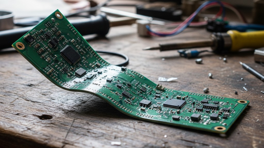
This failure is counterintuitive because the root cause of warpage isn’t abstract copper imbalance, but asymmetric heating during the reflow cycle. Adding copper changes a board’s thermal mass and heat distribution. When that copper is placed without understanding how it affects heating symmetry at peak reflow temperatures, it creates new thermal imbalances—often worse than the original. The board twists as different regions heat at different rates and hold that heat for different durations, driving differential expansion that the substrate cannot absorb without deforming.
The answer isn’t to abandon copper balancing. It’s to recognize that stackup symmetry, controlled local copper density, and proper panel support are far more effective strategies than blanket thieving. These approaches address thermal asymmetry directly, rather than treating copper distribution as a purely geometric exercise. To understand when thieving makes things worse, you first have to understand the thermal mechanics that govern a board at 250°C.
The Thermal Mechanics of Reflow Warpage
Warpage is fundamentally a problem of constrained differential expansion. A printed circuit board is a composite of materials with different coefficients of thermal expansion (CTE), thermal masses, and thermal conductivities. When this composite is heated rapidly and unevenly, internal stresses build. If those stresses exceed the substrate’s elastic limit at high temperatures, the board deforms. The deformation may be temporary, relaxing as the board cools, or it can become permanent if the substrate yields or the cooling process locks in the strain.
Why Differential Expansion Creates Twist
A material’s CTE describes how much its dimensions change per degree of temperature increase. Copper’s CTE is about 17 ppm/°C. FR-4 laminate, the most common PCB substrate, has a similar in-plane CTE of 14-17 ppm/°C, but its through-thickness CTE is much higher, often 60-70 ppm/°C. This mismatch means that as temperature rises, copper and FR-4 want to expand at different rates.
Bonded together in a laminate, neither material can expand freely. The copper restrains the FR-4, and the FR-4 restrains the copper, creating internal stress. If the board heats uniformly and the copper is distributed symmetrically through the stackup, these stresses are manageable. The board expands evenly, the stackup’s symmetry keeps the neutral axis centered, and the balanced forces on the top and bottom keep the board flat.
Uniform heating, however, is a luxury. When one region of a board gets hotter than another, it wants to expand more. Tethered to the cooler region, it can’t, and stress builds along the boundary. If the thermal gradient is severe and consistently oriented—one side of the board always hotter than the other—the board will bow or twist to relieve the stress, seeking a new equilibrium shape that minimizes internal strain energy.
Timing is critical. FR-4 becomes significantly more compliant as it approaches and exceeds its glass transition temperature (typically 170-180°C). During the reflow peak, at or above 240°C, the substrate is at its least rigid. This is its moment of maximum vulnerability. A thermal imbalance at this point will warp the board. If that warp exceeds the yield point of the softened resin, the board will not fully recover its shape upon cooling.
Copper: Thermal Mass and Heat Highway
During reflow, copper plays two roles: it acts as thermal mass and as a heat highway. Both are consequences of its physical properties—high specific heat and exceptionally high thermal conductivity compared to FR-4.
As thermal mass, copper dictates the energy required to raise its temperature. A board with heavy copper planes requires more energy and time to reach reflow temperature than one with sparse traces. This means areas with high copper density heat more slowly than areas with low density. If a board has large, solid copper planes on its left half and only light routing on its right, the left half will lag in temperature during ramp-up. At any given moment, the right half is hotter, creating the thermal asymmetry that drives warpage.
As a heat highway, copper’s high thermal conductivity (roughly 400 W/m·K versus FR-4’s 0.3 W/m·K) allows it to redistribute heat rapidly. A large copper plane doesn’t just heat slowly due to its mass; it also spreads heat away from localized hot spots, evening out the temperature across its surface. While this can be beneficial, it also means that the presence or absence of copper creates fundamentally different thermal zones. A region with a solid plane has a slow, uniform thermal response. A region with only traces has a fast, localized response.
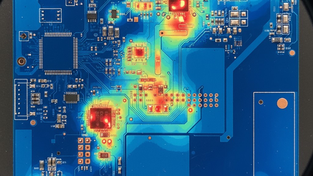
Copper doesn’t just add mass; it fundamentally restructures the board’s thermal landscape. This is why its distribution must be considered a matter of thermal design, not just fabrication uniformity.
How Copper Distribution Governs Heating Symmetry
Thermal symmetry means that all regions of the board reach the same temperature at roughly the same time. While perfect symmetry is impossible, the goal is to minimize thermal gradients, particularly during the peak reflow phase when the board is most compliant.
Copper distribution dictates this symmetry by defining the board’s thermal mass and conductivity maps. A board with uniform copper density has a relatively uniform thermal response, absorbing heat as a coherent whole. A board with highly non-uniform copper becomes a patchwork of zones with different thermal time constants—dense areas lag while sparse areas lead.
The problem is compounded in multilayer boards. Consider a six-layer design where power planes cover only half the board area. That half of the board has dramatically higher thermal mass. During reflow, it heats more slowly, creating a persistent gradient from the sparse side to the dense side. If this gradient runs along the board’s length, it bows. If it has rotational asymmetry, it twists.
The reflow profile can exacerbate this. A profile’s soak zone is designed to equalize temperatures before the final ramp to peak, but it isn’t infinitely long. If a board has a significant thermal mass imbalance, the soak may not be enough. As the oven spikes to 240-250°C, the low-mass regions overshoot first while the high-mass regions are still catching up. This is the critical window where warpage begins.
Once distinct thermal zones form, they interact. A large copper plane in a dense area pulls heat into itself, holding that area cooler for longer and steepening the gradient with adjacent sparse areas. Lacking the thermal buffer of copper, those sparse areas heat rapidly. The gradient persists through the peak, and the board warps.
The Blanket Thieving Trap
The instinct to apply copper thieving is rooted in valid fabrication concerns like uniform etching and plating. But when applied as a blanket fill to meet a target percentage, thieving often creates the very thermal asymmetry it was meant to prevent.
It becomes the problem.
When Added Copper Creates New Imbalances
Thieving increases the thermal mass of the areas where it is added. On a board with functional copper concentrated in some areas and sparse routing in others, thieving is typically added only to the sparse regions. Those areas, which previously had low thermal mass and heated quickly, now heat more slowly.
This doesn’t remove the heavy functional copper; it just shifts the thermal balance. If the thieving is aggressive enough, it can shift the balance too far. The previously sparse area might now have a thermal mass comparable to the functional areas, but with a different geometry, creating a new and unpredictable imbalance.
The issue isn’t just density, but location and intent. If thieving is placed in a region that was already cooler during reflow, adding thermal mass there makes it even cooler, steepening the gradient. Blanket thieving strategies don’t make this distinction; they apply fill based on a density target, not thermal analysis. The result is often more copper where it shouldn’t be.
A specific failure mode occurs when thieving is added to outer layers directly above inner-layer planes. This surface mass absorbs heat from the oven and conducts it inward. If the inner layers already have high thermal mass, the outer thieving increases the total mass of that stack without improving heat penetration to the core. The core lags further, the surface-to-core gradient increases, and through-thickness stress builds, driving in-plane warpage as the surface layers expand more than the core.
Thieving at Peak Temperature
The reflow peak is the moment of maximum thermal stress and minimum substrate rigidity. Any thermal imbalance that exists here will have the greatest impact because the board’s ability to resist deformation is at its lowest. Thieving locks in a thermal structure. If that structure creates an imbalance that manifests at peak temperature, it will do so every time the board goes through an oven.
The oven cannot solve an imbalance intrinsic to the board’s construction. If the oven increases heat to bring cool, high-mass regions up to temperature, the thermally responsive regions will overshoot. The board reaches its peak with different areas at different temperatures. The hotter areas expand more, the cooler areas expand less. The board is soft. It twists. As it cools, the deformation can become permanent, leaving components out of position and solder joints compromised—a failure invisible to standard electrical tests.
Stackup Symmetry: The Primary Warpage Control
The most effective way to control warpage is to design a board stackup that is thermally and mechanically symmetrical about its central plane. This ensures that thermal expansion forces on the top half of the board are mirrored by equal and opposite forces on the bottom half. With no net bending moment, the board stays flat.
Balancing Copper, Plane to Plane
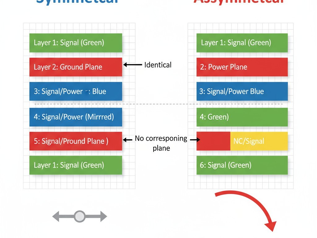
Stackup symmetry means that for every copper feature on one layer, a corresponding feature exists on a layer equidistant from the board’s center. In a six-layer stackup, layer two should mirror layer five, and layer three should mirror layer four. If layer two is a solid ground plane, layer five should be a solid ground plane of the same area and thickness. This mirroring balances the thermal mass through the board’s thickness, ensuring the top and bottom halves heat at the same rate. The stress from CTE mismatch is still present, but it’s symmetric, so the board expands uniformly without bending.
The outer layers (one and six) should also be balanced. While identical copper is often impossible due to component placement, the goal is to keep the overall copper weight and distribution as close as possible. Material selection matters, too; core and prepreg thicknesses should be mirrored about the center to align the mechanical and thermal neutral axes, maximizing the board’s resistance to warpage.
When Stackup Modification Is Constrained
Perfect symmetry isn’t always possible. Cost may fix the layer count, or the design may require planes that can’t be mirrored. A board needing a large ground plane on layer two without a corresponding plane on layer five is inherently asymmetric.
In these cases, one approach is to use a non-functional, partial plane on the mirror layer. A hatched or meshed copper pour covering the same area adds thermal mass and improves symmetry without creating a solid electrical plane. This compromise can often reduce warpage to acceptable levels. The trade-off is increased copper usage for a non-functional feature, a cost that must be weighed against the yield impact of warpage.
When stackup symmetry is compromised, the board is more vulnerable to warpage, and the margin for error is slim. Adding aggressive thieving to an already asymmetric stackup is particularly risky, as it can interact with the existing imbalance in unpredictable ways.
Controlled Copper Density Without Aggressive Fill
If stackup symmetry is the primary defense, controlled copper density is the tactical tool for managing local imbalances. The goal is to add copper only where needed, in the amount needed, without creating new thermal problems. This requires a shift from global to local balancing, paired with mechanical support during reflow.
Local Balancing over Global Fill
Local balancing means addressing copper density in specific regions rather than applying a uniform fill pattern everywhere. The process starts with identifying concentrated and sparse copper areas, then using thermal intuition to decide where added copper will help versus where it will hurt.
If a very low-density area is surrounded by regions of moderate density, adding modest thieving can soften the thermal discontinuity. The goal isn’t to hit a global density target, but to reduce the gradient. If the surrounding areas have 30% copper and the sparse area has 5%, bringing it to 15% may be enough. Pushing it to 30% with aggressive thieving may overshoot the goal.
This also means avoiding thieving where it isn’t needed. Adding copper to a thermally stable area just to meet an arbitrary global density target adds unneeded thermal mass and shifts the balance. This is the trap of rigid design rules that ignore distribution. The geometry of the fill also matters. Hatched or dotted patterns create lower effective thermal mass than solid fills and allow for finer control. They can satisfy fabrication minimums without dominating the thermal behavior of a region.
The practical approach: use coarse, low-density fills only where required to meet a fabricator’s minimum. Justify every addition of copper on a region-by-region basis, not as a global operation.
Panel Support and Tooling
Panel support is a mechanical strategy that complements thermal design. Even a board with some thermal imbalance can be kept flat if it is adequately supported in the reflow oven. The support constrains the board’s ability to deform as it passes through its most vulnerable, high-temperature state.
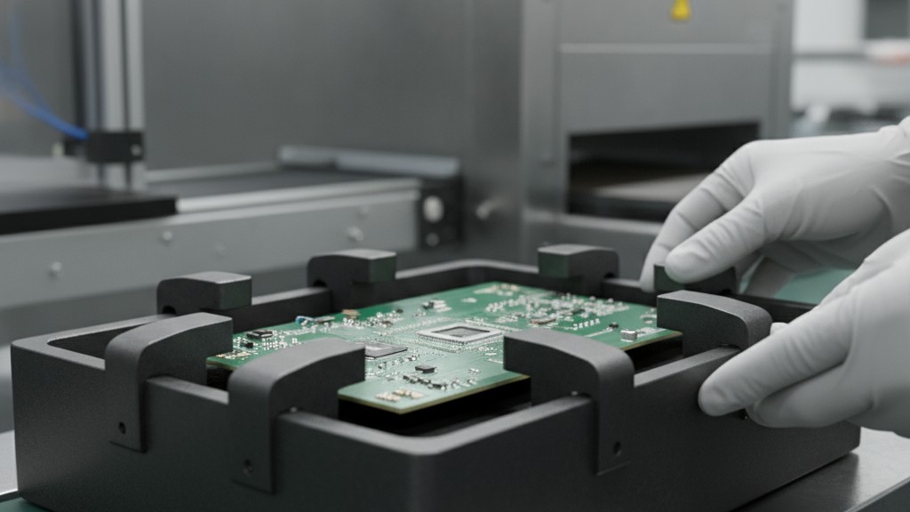
A board still attached to its panel is constrained by the panel rails, which are more rigid and hold the entire assembly flat. For this reason, many high-reliability assemblies are reflowed in panel form. For individual boards, a reflow carrier or fixture provides the same function. These rigid frames, often made of low-CTE materials like graphite composite, hold the board flat by mechanical force. The trade-off is the carrier’s own thermal mass, which can affect the reflow profile.
Support doesn’t eliminate the thermal imbalance; it suppresses the resulting warpage. The board is still under internal stress, which can affect solder joints. Support is therefore a mitigation strategy, not a cure-all. The best results come from minimizing thermal imbalance through design and using mechanical support to manage residual risk.
Deciding When Thieving Is Justified
Copper thieving isn’t inherently bad. It becomes a problem when applied blindly, as a substitute for proper stackup design and density control. The decision to use it should be deliberate.
When is it justified?
- To meet fabrication minimums. Many fabricators require a minimum copper density (e.g., 20-30%) for uniform plating. If a design falls below this, some fill is mandatory. In this case, add only enough copper to meet the minimum, using low-density patterns. This is a fabrication constraint, not a thermal optimization.
- When thermal simulation shows a clear benefit. In some cases, modeling may show that adding copper to a specific hot spot can increase its thermal mass just enough to bring it into balance with adjacent areas. This is the correct, surgical use of thieving as a thermal tool, the opposite of a blanket fill.
- When the board is inherently rigid. Thick, small, or highly symmetric boards may tolerate aggressive thieving without issue. The decision is risk-based. If a board is marginal—thin, large, or asymmetric—thieving must be tightly controlled.
The guiding principle is parsimony. Add copper only when there is a defined need and a clear understanding that it won’t create a worse problem. Default to minimal, localized thieving. Rely first on stackup symmetry for thermal balance and use panel support to manage residual risk. Treat thieving as a targeted correction, not a standard finishing step. Your boards will emerge from reflow flat, and your assembly yield will reflect that design discipline.
