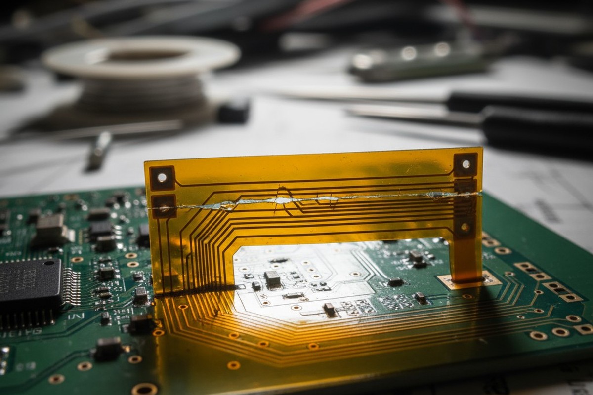
A rigid-flex circuit can look perfect in CAD, routing elegantly through a three-dimensional product enclosure, and still fracture after five hundred field cycles. This isn’t a simulation error or a design rule oversight. It’s a failure that stems from the gap between what a design file specifies and what the physics of copper fatigue will tolerate. The cosmetic perfection of a rendered stackup says nothing about grain structure, little about stress distribution in the coverlay, and less about the manufacturing realities that determine whether a stiffener edge concentrates or diffuses strain.
Reliability in dynamic flex applications is earned by managing four variables that govern copper’s resistance to cyclic stress: grain direction, trace geometry, coverlay windowing, and stiffener placement. Grain direction establishes the foundation of fatigue endurance. Trace routing either distributes or concentrates stress. Coverlay windows position the neutral bending axis. Stiffeners control the critical transition zone where bending begins and stress spikes.
These are not independent decorations applied to a layout. They are interdependent mechanical choices that must align with the physical behavior of rolled copper foil under repeated strain. Understanding the causal logic behind these choices is the difference between a design that fails and one that endures.
The Mechanics of Copper Fatigue
Copper fails under repeated bending because it is a polycrystalline metal subject to cumulative plastic deformation. Each flex cycle strains the copper beyond its elastic limit in localized regions, especially at the outer surface of the bend where tensile stress is highest. The material does not return to its original state. Instead, dislocations within the grain structure move and accumulate, work-hardening the copper and creating nucleation sites for cracks. Over hundreds or thousands of cycles, these microcracks propagate along grain boundaries until a complete fracture occurs. Given enough cycles at a sufficient strain, failure is inevitable. The designer’s task is to reduce that strain and dramatically increase the cycles required for a crack to even begin.
Grain Structure and Crystallographic Slip
Electrodeposited copper foil, common in many flex circuits, has a columnar grain structure perpendicular to the foil plane. Rolled annealed copper foil, the correct choice for dynamic applications, has elongated grains aligned with the rolling direction. When copper bends, plastic deformation occurs as dislocations move along slip planes within each grain. Grain boundaries act as barriers, causing dislocations to pile up and increasing local stress. The orientation of these boundaries relative to the applied stress dictates how easily dislocations move and how quickly the material fatigues.
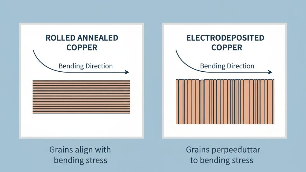
In rolled copper, bending parallel to the elongated grains forces dislocations to cross fewer boundaries, distributing strain more evenly and delaying crack nucleation. Bending perpendicular to the grain direction forces dislocations across many boundaries in a short distance, concentrating strain and accelerating failure. The difference is not subtle. A flex circuit bent perpendicular to the grain can fail in two thousand cycles, while the same geometry bent parallel might survive twenty thousand. The grain structure is invisible in the CAD file, yet it is the dominant variable in fatigue performance.
Stress Concentration at the Bend Axis
When a flex circuit bends, its outer radius experiences tension, its inner radius compression, and a neutral axis somewhere between them experiences zero stress. The magnitude of stress is proportional to the distance from this neutral axis and inversely proportional to the bend radius. Sharper bends and thicker constructions both produce higher stress.
This stress is not uniform. It peaks at the center of the bend and drops toward the rigid sections. Any feature that disrupts this stress field—an abrupt change in trace width, a poorly placed stiffener—creates a stress concentration. Fractures initiate at these concentrations, not at random. Flex circuit design, then, is not about simply choosing a bend radius. It is about identifying where stress will peak, keeping those peaks below copper’s fatigue limit, and eliminating geometric disruptions that create new ones.
1. Copper Grain Direction: The Primary Variable
For any application targeting more than a few thousand cycles, the rolling direction of the copper foil must be specified perpendicular to the bend axis. This is not a guideline; it is a material constraint derived from the anisotropic fatigue behavior of rolled copper. A fabricator who does not control grain direction delivers a coin flip—a fifty-percent chance the copper is oriented in its weakest direction. A designer who does not specify it has delegated the most important reliability variable to chance.
Specifying Rolling Direction
The fabrication drawing must include a grain direction indicator for every dynamic flex region. For a single-axis hinge, this is a single arrow with a note, such as “Copper rolling direction per arrow, perpendicular to bend axis.” The designer must also confirm the fabricator sources rolled annealed copper with a defined grain orientation. Not all can. Low-cost or quick-turn suppliers often use electrodeposited foil or purchase rolled copper sheets without tracking orientation.
If a circuit bends in multiple directions, it may be impossible to align the grain favorably for all axes. The designer must then prioritize the axis with the highest cycle count or strain and accept reduced performance elsewhere. This trade-off must be documented and communicated, not left implicit. The fabricator’s process capability is key. A supplier using continuous-roll processing can easily align the panel to match the specification. A sheet-fed process may offer less control or incur extra cost. This must be confirmed during design review.
When Grain Direction Control Isn’t an Option
If grain direction cannot be controlled, the design must compensate through geometry. Increase the bend radius to reduce strain. Widen traces to lower current density and heating. If the application permits, reduce the target cycle count. Use hatched or curved traces instead of straight runs to distribute stress. Specify thinner copper where possible, as it bends with lower stress for a given radius. None of these strategies fully recover the performance of correct grain alignment, but they can make an uncontrolled design viable for applications in the low thousands of cycles.
2. Trace Routing Geometry
The path a trace takes through a flex zone determines how it interacts with the stress of bending. Routing for dynamic flex is not about minimizing trace length or maximizing density. It is about creating a geometry that distributes stress evenly and avoids discontinuities.
Trace Orientation
Ideally, all traces should run parallel to the bend axis, entering and exiting the flex zone along its long edges. This keeps each trace within a region of nearly constant stress, rather than forcing it to traverse the gradient from tension to compression. This simple choice can improve fatigue life by a factor of three or more compared to perpendicular routing, even with correct grain alignment.
When traces must cross the bend axis—for instance, to connect components on opposite sides of a fold—minimize the number of crossings. Make those traces as wide as current and impedance requirements allow, as wider traces tolerate higher stress. If multiple traces must cross, stagger them along the length of the flex zone rather than grouping them at the center where stress peaks.
Width, Spacing, and Hatching
A trace that changes width in the flex zone creates a stress riser at the transition. Maintain a constant trace width throughout the entire flex zone. Any necessary width changes should occur well within the rigid section, at least five trace widths away from the flex boundary.
For designs needing controlled impedance or high current in a narrow flex width, hatched traces offer a compromise. A hatched trace is a solid copper region with periodic slots running parallel to the bend axis. This creates a series of narrow fingers that flex more easily, reducing the copper layer’s effective stiffness and lowering stress. The trade-off is reduced current capacity and more complex fabrication.
Trace spacing should be generous. Closely spaced traces create a stiffer copper layer that concentrates stress. A spacing of at least two times the trace width is a good starting point; for a very tight bend radius, increase that to three or four times the width.
Anchoring and Teardrops
The transition from a rigid section to a flex zone is a point of abrupt mechanical change and high stress. If a trace enters the flex zone with a sharp corner, that feature becomes the failure point. The trace will crack at its anchor, not in the middle of the bend.
Teardrops are the standard solution. A teardrop gradually widens a trace as it exits a via or pad. At the rigid-to-flex transition, this concept applies to the entire anchor region. The trace should widen as it approaches the flex boundary and then taper back to its required width once clear of the high-stress zone. This distributes the stress gradient over a longer distance. Avoid anchoring traces directly to vias at the boundary. Offset any necessary vias at least one millimeter into the rigid section and use smooth, curved routes into the flex zone.
3. Coverlay Windowing to Control the Neutral Axis
The neutral axis is the plane within a flex circuit that experiences zero strain during bending. In a perfectly symmetric stackup, this axis lies within the copper layer itself, minimizing stress. However, standard flex construction is asymmetric. The protective coverlay film is typically thicker than the base polyimide beneath the copper, which shifts the neutral axis away from the copper and toward the thicker coverlay. This seemingly small shift can increase copper strain enough to reduce fatigue life by 30-50%.
Coverlay windowing is a technique to restore symmetry. It involves removing the coverlay and its adhesive in the highest-stress region of the bend, leaving only the base polyimide and copper. This shifts the neutral axis back toward the copper, dramatically increasing fatigue life. The trade-off is that the copper is exposed, so this technique is only viable where environmental protection is not needed or can be added later.
The window geometry is critical. It should be centered on the bend axis and extend at least three times the bend radius along the axis. The window’s edges must be at least two millimeters from the rigid-flex boundary to avoid creating a new stress concentration where the stackup stiffness abruptly changes. If coverlay cannot be removed, an alternative is to specify a symmetric stackup from the start by using a thin polyimide layer laminated on top of the copper. This costs more but achieves the same benefit without exposing the copper.
4. Stiffener Placement for Transition Management
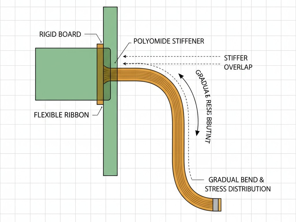
The rigid-to-flex transition is the highest-stress region in most dynamic applications. The rigid section doesn’t bend, forcing all deformation into the first few millimeters of the flex zone. Stiffeners are used to manage this transition, controlling where bending starts and lengthening the transition zone to reduce peak stress.
A stiffener is a material layer, typically polyimide film, bonded to the rigid section and extending just short of the bend area. It prevents bending where it is applied, forcing the bend to begin at its edge. By offsetting this edge from the actual rigid-flex boundary, the designer creates a controlled zone where stiffness decreases gradually, spreading the strain over a longer distance.
Stiffener Material and Edge Geometry
Polyimide film is the most common stiffener material for dynamic flex. It is stiff enough to control the bend location but flexible enough to avoid creating a hard, stress-concentrating edge. Metal stiffeners are generally unsuitable, as their hard edges create sharp stress risers.
The stiffener edge must be precisely positioned. A good rule of thumb is to place the edge one to two times the bend radius away from the bend’s centerline. The edge itself should be tapered, not cut square. A tapered edge creates a gradual stiffness transition. This can be achieved by skiving the stiffener material, using multiple staggered layers, or sourcing inherently tapered films. The taper should be at least three millimeters long for high-cycle applications.
For a circuit that bends from a central rigid section, stiffeners define the boundaries of the flex region. The length of this zone is critical; it must be long enough to accommodate the bend without overstressing the copper. A reliable design rule is to make the flex zone at least six times longer than the bend radius. For a 5 mm bend radius, the stiffener edges should be at least 30 mm apart.
Design Validation Beyond the CAD Model
A rigid-flex layout that passes all software design rule checks can still fail. CAD tools describe geometry; they do not account for grain direction, neutral axis position, or stress concentrations at a stiffener edge. Validation requires stepping outside the CAD environment to confirm that the design aligns with material physics and that the fabricator can execute it as intended.
This starts with a direct conversation with the fabricator to confirm they can source and control rolled copper grain direction. It continues with a review of their actual stackup materials—coverlay thickness, adhesive type, registration tolerances—to recalculate the neutral axis position based on reality, not on generic assumptions. The fabricator’s stiffener placement process, including positional accuracy and edge tapering capabilities, must also be incorporated into the design.
Prototyping reveals the truth. Cracks that initiate at the rigid-flex boundary point to insufficient stress relief, likely due to stiffener placement or poor trace anchoring. Cracks in the center of the flex zone suggest incorrect grain direction or too tight a bend radius. Each failure mode points to a specific variable that needs correction.
For targets exceeding ten thousand cycles, accelerated testing is essential. This involves flexing prototypes at a higher frequency or tighter radius to accumulate cycles quickly. While testing cannot substitute for sound design, it can reveal complex interactions between variables that are difficult to predict. The design process is iterative: design based on physics, review with the fabricator, and test the physical prototype. The CAD model is the starting point, not the proof.
