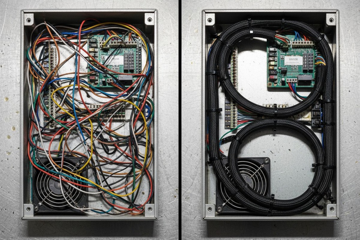
The most accurate way to judge the engineering health of a box build is to look at the parts the customer will never see. External enclosures can be polished, powder-coated, and branded to perfection, but pop the lid, and the truth comes out. If the internal cabling looks like a nest of vipers—wires under tension, service loops missing, bundles blocking airflow—the system is already failing. It just hasn’t stopped working yet.

Aesthetics in cabling aren’t about vanity; they are a proxy for reliability. When we open a chassis and see a “rats nest,” we don’t just see a mess. We see potential energy waiting to turn into kinetic failure. A cable routed haphazardly is a cable that will rub against a standoff until the insulation fails. A bundle stuffed against a fan intake is a thermal wall. In high-stakes industrial integration, the difference between a box that runs for ten years and one that comes back on an RMA pallet in six months is often entirely defined by the geometry of the wires inside.
If It Isn’t on the Drawing, It Isn’t in the Box
The single greatest failure mode in box build assembly is relying on tribal knowledge. You might have a brilliant technician who knows exactly how to route a SATA cable so it doesn’t cross the high-frequency signal lines. But if that technician goes on vacation, or if production scales from ten units to a thousand, that knowledge evaporates. We have seen prototypes that functioned perfectly on the bench fail EMI testing immediately upon scaling because the “standard” routing wasn’t documented. The assembler on the line simply took the shortest path between two points, drifting a signal wire right over a noisy transformer.
Consistency requires a routing diagram that is as rigorous as the PCB schematic itself. This means defining the exact path, the tie points, and the bundle separation distances. Merely specifying “connect J1 to J2” is insufficient; you have to define the road taken to get there. This is where the distinction between IPC/WHMA-A-620 Class 2 and Class 3 standards often blurs in practice. While a contract might only strictly require Class 2, the logic of routing—avoiding sharp edges, maintaining bend radii—is a physics requirement, not just a paperwork one. If you don’t document the path, you are effectively redesigning the product with every single unit built.
Cable Routing is a Fluid Dynamics Problem
There is a pervasive confusion in thermal management where engineers blame the fans for overheating when they should be blaming the harness. You can spec the highest CFM fans on the market, but if you place a two-inch thick bundle of cables directly across the intake vent, you have built a dam, not a cooling system. We frequently encounter “thermal failures” where the root cause is simply a lack of routing discipline.

Airflow is a fluid, and it follows the path of least resistance. When cables are treated as an afterthought—stuffed into the remaining negative space once the boards are mounted—they almost always occupy the air gap meant for convection. A disciplined build treats cable bundles as solid objects in the thermal model. By routing cables along the chassis rails and using the natural corners of the enclosure, you maintain the laminar flow required to keep processors and power supplies within their derating curves. If you look at a thermal image of a chassis and see hot spots near the intake, check the cabling before you redesign the heat sink.
Vibration Turns Tension into Failure
A wire under tension is a slow-motion tragedy. Copper is a soft metal, and insulation is plastic; both are subject to “cold flow” (creep) when stressed. If a cable is pulled tight against a metal edge or even against its own connector, time and vibration will inevitably cause that material to move. In automotive or industrial environments, where vibration is constant, a tight cable acts like a guitar string. It has a resonant frequency. When the system hits that frequency, the connector pins fret, the plating wears through, and you get the most dreaded of all field failures: the intermittent ghost bug.
The instinct for many is to add more zip ties to hold everything down, but this is a double-edged sword. Over-constricting a bundle with high-tension ties can crush the insulation, altering the impedance of high-speed lines and creating weak points. The goal is to support the wires, not to strangle them. We look for “strain relief” in the literal sense—relieving the strain from the termination point. The connector should carry the signal, not the mechanical load of the wire’s weight. If you disconnect a cable and it immediately springs back two inches, it was installed under tension, and it was already dying.
The Service Loop as Insurance
Designers often forget that a human hand will eventually have to reach inside the box. There is a specific kind of frustration reserved for field technicians who open a chassis to replace a fan or a battery, only to find the cables are so short they cannot move the component without disconnecting the entire main harness. This is the “knuckle-buster” design, and it drives up service costs and technician injury rates.

The “service loop”—a deliberate extra length of wire, usually looped neatly before the termination—is your insurance policy. It looks like waste to a cost-cutter. Why pay for three extra inches of copper times a thousand units? You pay for it because when a connector needs to be re-terminated in the field, that extra length is the difference between a five-minute repair and a complete harness replacement. We have seen five-figure medical carts grounded because a ten-cent connector failed and there was zero slack to strip and re-crimp a new contact. The service loop acknowledges that the future is uncertain and that maintenance is inevitable.
The Weaponization of Zip Ties
We also need to talk about safety in the invisible places. A standard nylon cable tie, if cut with a pair of side cutters or pliers, leaves a sharp, jagged tag end. In the tight confines of a server rack or industrial controller, that tag end is effectively a razor blade. It is a blood hazard for anyone who reaches in later.
This is why the specific tooling matters. Using a calibrated tension gun with an automatic flush cut-off isn’t just about being fancy; it’s about safety and consistency. The tool tightens the tie to a pre-set tension (so you don’t crush the wire) and slices the tail flush with the head (so you don’t slice the technician). If we see jagged tie ends in a prototype, we know the assembly process is immature. It suggests a “make it work” mentality rather than a manufacturing mindset.
Reliability is Quiet
The best box build is boring. It doesn’t rattle, it doesn’t overheat, and when you open it up five years later, the cables are exactly where they were the day it left the factory. Achieving that silence requires treating the cabling not as “stuffing” but as a critical mechanical system. It requires the discipline to document the invisible paths, the foresight to leave slack for the future, and the rigor to respect the physics of copper and airflow.


