Vibration is the silent, persistent enemy of automotive electronics. While a printed circuit board (PCB) sits static on a designer’s CAD screen, the reality of its operational life is a chaotic mess of random vibration profiles, thermal shock, and mechanical resonance. In this environment, a large electrolytic capacitor isn’t just an energy storage device. It is a hammer swinging at its own legs.
The Invisible Stressor
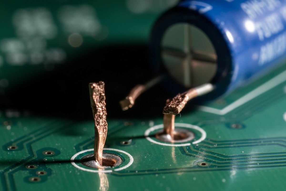
When a vehicle hits a pothole, or an engine hits a resonant frequency, physics acts mercilessly on components with high centers of gravity. A 35mm tall electrolytic capacitor, secured only by two copper leads, becomes a cantilever beam problem. Under standard random vibration profiles like ISO 16750-3, the capacitor oscillates. It may not fail in the first hour, or even the tenth. But copper is a ductile metal that work-hardens under repeated stress.
Eventually, the metal fatigues. The microscopic crystalline structure aligns, becomes brittle, and shears. This often happens invisibly, inside the component casing or right at the PCB surface, leading to intermittent failures that are notoriously difficult to diagnose. The failure mode looks like mechanical fatigue, but the root cause is a lack of support. If the component’s mass exceeds the structural capacity of its leads—a certainty for large capacitors in automotive applications—external support stops being an option. It becomes a requirement.
The Manual Application Trap

For decades, the industry standard for this support was a tube of RTV silicone and a technician with a caulk gun. This approach relies entirely on the “craftsmanship” of the operator. In a high-volume, high-reliability environment, relying on craftsmanship for a critical safety characteristic is a procedural failure. Humans are inherently variable. One operator might apply a perfect fillet that supports the capacitor base. The next might apply a glob that sits too high, or a smear that bridges adjacent pads.
Think of this as the “dirty hands” problem. In a cleanroom, we automate placement to avoid contamination and ensure precision. Yet, we often allow manual dispensing of adhesives, introducing a massive variable into the process. There is a well-documented history of failures where manual silicone application led to disaster. In one case, silicone residue transferred from an operator’s gloves to the gold finger contacts of a PCIe connector. The silicone migrated, formed insulating silica under electrical arcing, and severed the connection. That is the hidden cost of manual labor: the risk of contamination and the impossibility of consistent volume control.
Worse, the materials chosen for manual application are often chemically unsuited for electronics. Acetic cure silicones, which smell like vinegar, release acetic acid as they cure. This acid attacks copper traces and lead finishes, corroding the board before it even leaves the factory. While neutral cure silicones exist, the manual process cannot guarantee the geometry required for true vibration resistance. Relying on a process that cannot pass a gauge R&R study (Repeatability and Reproducibility) for a critical automotive application borders on professional malpractice.
Chemistry is Not a Commodity
Selecting the correct staking material is as critical as the process itself. There is a temptation, often driven by upfront BOM costs, to reach for consumer-grade solutions like hot melt glues (EVA adhesives). This is a fundamental error. An automotive dashboard in Arizona can reach internal temperatures of 85°C or higher. At those temperatures, standard hot melt adhesives soften and lose structural integrity. The capacitor leans, the glue yields, and the leads snap. You are essentially relying on a material that turns into a lubricant exactly when you need it to be a structural support.
Engineers also frequently confuse environmental protection with mechanical support, specifying heavy conformal coating in the hopes that it will secure large components. This misunderstands the physics. Conformal coating is a raincoat; staking is a seatbelt. A dip coat or spray of acrylic or urethane, even if applied thickly, lacks the shore hardness and tensile strength to stop a 20-gram capacitor from oscillating. You need a material specifically engineered for structural bonding, typically with a Shore Hardness in the D-scale range (e.g., D80), not the softer A-scale used for gaskets.
The interaction between the adhesive and the component body is equally nuanced. A material that is too hard, or has a Coefficient of Thermal Expansion (CTE) that vastly mismatches the capacitor casing, can crack the component during thermal cycling. If the adhesive expands faster than the aluminum, it crushes the component. If it shrinks too much, it pulls away. The ideal material is often a UV-cure or thermal-cure epoxy with a thixotropic index that allows it to stand tall without slumping, providing a “tripod” of support rather than a suffocating collar. While UV stabilizers have limits over 15+ year lifespans in direct sunlight, for internal electronics, the chemical bond of a UV-cure acrylic or epoxy is far superior to the mechanical grip of a silicone blob.
Automation as a Geometry Problem

Automated dispensing transforms the problem from one of “gluing” to one of geometry. We aren’t trying to bury the component; we are creating a specific structural support system. A robotic dispensing valve, programmed with volumetric precision, places dots of adhesive at specific coordinates relative to the capacitor’s center of mass.
This process creates a “tripod” or “buttress” effect. By placing three discrete dots around the base of a radial capacitor, the automation secures the component against movement in the X, Y, and Z axes while leaving gaps for thermal expansion. This prevents the “choking” effect seen with full encapsulation. The machine validates the presence of the component, checks the Z-height of the board to account for warpage, and dispenses exactly the programmed volume—down to the milligram.
This precision also clears up the confusion regarding “underfill.” In Ball Grid Array (BGA) applications, underfill flows under the part. For large electrolytic capacitors, flowing material underneath can be detrimental. If gas trapped under the capacitor expands during reflow or operation, it can pop the component off the board or rupture the seal. Automated staking applies material to the side and base (fillet), securing the part without trapping volatiles underneath.
The economic argument against this automation usually centers on the NRE (Non-Recurring Engineering) cost of programming and fixture design. This view is myopic. The cost of a single field failure—a truck recalled, a line down, an 8D report requiring weeks of engineering investigation—dwarfs the cost of the dispensing robot. When you factor in the “hidden factory” of rework required to clean up messy manual silicone application, automation often becomes the budget option over the product’s lifecycle.
The Shaker Table Verdict
Physics does not care about your budget or your intent; it only respects mass and acceleration. The only way to truly validate a staking process is on a vibration table (shaker).
In a typical validation scenario, a power board with unstaked 35mm capacitors is strapped to a shaker table running a random vibration profile. Often, within less than an hour, fatigue sets in. The leads shear, and the capacitors detach, rattling around inside the enclosure like bullets. This isn’t theoretical. It is a repeatable outcome of mass versus copper. When the same board is run with automated staking using a UV-cure epoxy, it survives the full duration of the test without significant shifts in resonance.
It is worth noting that the rise of Electric Vehicles (EVs) introduces new vibration challenges. The high-frequency harmonics from electric motors and gearboxes differ from the lower-frequency rumble of internal combustion engines. While standard profiles cover the basics, the industry is still mapping the long-term effects of these higher frequencies. Regardless of the frequency, the solution remains the same: rigid, repeatable mechanical support is the only defense against fatigue.
Reliability is a Choice
The decision to automate adhesive dispensing is a decision to sleep at night. It removes the variability of the human hand from a process that demands the precision of a machine.
If you rely on manual RTV to keep your power electronics intact, you are betting against probability. The receipts—in the form of sheared leads, cracked solder joints, and expensive recalls—are piled high in the industry’s history. Automated staking isn’t gold-plating the product. It is ensuring that the product survives the journey it was designed for.


 Circuit Board Assembly")
