The scenario is frustratingly common. A complex board, dense with heavy copper planes, emerges from the reflow oven. Inspection reveals a cluster of head-in-pillow (HiP) defects under a large BGA—insidious open circuits where the solder ball and paste failed to coalesce. The immediate instinct is to increase the solder paste volume. It seems logical: if the connection isn’t forming, just add more material.

This instinct is wrong. At Bester PCBA, we have seen this approach fail time and again. For high thermal mass assemblies, drowning the pads in paste ignores the true culprit. The problem isn’t a lack of solder; it’s a momentary, catastrophic loss of coplanarity driven by the physics of heat transfer. The solution lies not in a bigger stencil aperture, but in a disciplined control of your entire assembly process.
The Anatomy of a Stubborn Defect: Warpage, Thermal Lag, and Failed Intuition
A printed circuit board is not an inert slab. It’s a composite of materials with wildly different thermal properties. When a board with significant thermal mass from heavy ground planes or a thick form factor enters a reflow oven, it resists temperature change, creating the perfect conditions for HiP defects.
The Core Challenge of High Thermal Mass
High thermal mass acts as a heat sink, causing profound thermal lag. While the board’s outer edges and top-side components heat up quickly, its inner layers and component-side ground planes absorb thermal energy much more slowly. This differential heating is the engine that drives dynamic warpage during reflow. The board physically distorts in the oven, and this distortion is neither uniform nor static.
Debunking the “More Paste” Myth: A Problem of Timing, Not Volume
Adding more paste fails because it treats HiP as a simple gap-filling problem. The gap, however, is dynamic. A larger paste deposit can slump, increase the risk of bridging, and still fail to contact a BGA ball that has temporarily lifted away due to warpage. The core failure is a misalignment in time: the solder paste melts and its flux activity is exhausted just as the BGA ball is at its furthest point of travel. By the time the board flattens out later in the profile, the paste is an oxidized, unwettable mass. The connection fails because contact wasn’t made at the precise moment of liquidus—a problem that volume alone cannot solve.
First Principles: The Physics of Coplanarity Drift
To solve this defect, you have to understand the forces at play. The HiP defect on a high thermal mass board is the story of a physical battle between the component and the PCB, fought with the weapon of temperature.
The Battle of Temperatures: How Thermal Gradients Drive Warpage

As the assembly travels through the reflow oven, a significant temperature difference, or delta-T, develops between thermally light and heavy areas. The BGA package, with its low thermal mass, heats up quickly. The area of the PCB directly beneath it, often tied to a massive ground plane, heats up far more slowly. This delta-T causes differential expansion. The BGA expands faster than the board underneath it, leading to a “smiling” warpage where the center of the component lifts away from the PCB. This creates the physical separation that defines the head-in-pillow condition.
The BGA vs. The Board: A Race to Liquidus
This warpage is most severe during the ramp-to-peak stage of the reflow profile—critically, this is also when the solder alloy reaches its liquidus temperature. The BGA’s solder balls, having heated quickly, are molten and ready to form a joint. The solder paste on the PCB pad, however, is still struggling to reach temperature because of the board’s thermal lag. The result is a critical misalignment. The BGA ball is liquid, but the paste is either not yet fully molten or the gap created by warpage is too large to bridge before the flux is spent. The connection fails.
The Thermal Playbook: Mastering the Reflow Profile
Since the root cause is thermal, the solution must be thermal. Your reflow profile is the most powerful tool for mitigating dynamic warpage. The goal isn’t just to melt solder, but to manage the delta-T across the entire assembly, ensuring everything arrives at liquidus at the same time and on the same plane.
Extending the Soak for Thermal Equilibrium
For high thermal mass boards, a longer and more carefully controlled soak zone is non-negotiable. A typical short soak profile that works for simple boards will be disastrous here. An extended soak period just below the solder’s melting point allows the stubborn, thermally heavy areas of the board to “catch up” to the lighter areas. By minimizing the delta-T across the assembly before the final ramp to peak, you drastically reduce the driving force behind warpage. The assembly enters the critical peak zone in a state of thermal equilibrium.
Disciplined Time-Above-Liquidus: Forging Flat Joints
Once in equilibrium, the time-above-liquidus (TAL) is the next critical parameter. A common mistake is a TAL that is too short, preventing full wetting, or too long, which degrades components and exhausts flux. For HiP, the goal is a TAL just long enough for two things to happen: for the molten solder to fully coalesce, and for the board and component to “relax” into a more planar state as temperatures equalize at peak. This discipline forges a flat, robust joint. For those with ovens that have fewer heating zones, achieving a long, stable soak can be challenging. In these cases, a slower overall ramp rate can simulate a longer soak, giving the board more time to equalize even if it extends the total profile time.
Beyond the Profile: Mechanical and Material Interventions
While the thermal profile is the star player, two other interventions provide a complete, robust solution by addressing the physical and chemical aspects of the problem.
Taming the Board with Proper Support
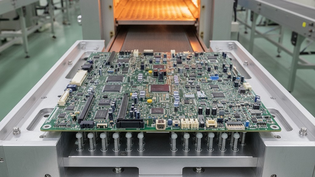
If thermal gradients are the engine of warpage, a lack of physical support is what lets it run wild. High thermal mass boards, especially large or thin ones, must be properly supported in the oven. Relying on simple edge conveyors is not enough. We strongly recommend dedicated support fixtures with pins that contact the board at the edges and in the center, particularly around the BGA. This mechanical support physically constrains the board, fighting its tendency to warp and dramatically improving coplanarity.
Choosing Your Weapon: High-Tack, Low-Slump Solder Paste
The solder paste itself is an active participant. When facing HiP on these boards, paste chemistry is crucial. You need a paste with exceptional tackiness and a robust flux package. A high-tack paste ensures that even if minor separation occurs, it maintains physical contact with the BGA ball. The flux must be designed to withstand a longer soak profile without losing activity, ready to clean oxides the moment liquidus is achieved. A paste with poor slump performance or a weak flux will only make things worse.
Verifying the Fix: From Process Control to X-Ray
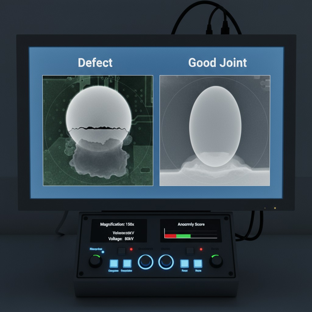
Implementing these changes is half the battle; verifying their success is the other half. Consistent thermal profiling is essential to ensure your process stays in control. A successful, documented profile that eliminates HiP should be regularly audited.
Ultimately, the definitive proof comes from inspection. While visual inspection can offer clues, the only way to be certain that HiP has been eliminated is through automated X-ray inspection (AXI). The cross-sectional view from an X-ray will clearly show a fully coalesced, homogenous solder joint, confirming that your disciplined, process-oriented approach has succeeded where simply adding more paste was doomed to fail.

