There is a seductive logic to the “black brick” approach in industrial electronics. You take a perfectly good PCB, drop it in a housing, and pour two-part epoxy over the assembly until it looks like a fossil trapped in amber. It feels substantial. It feels protected. And for a specific class of device—cheap, disposable, or deployed to the bottom of the Mariana Trench—it is the correct engineering choice. But for high-value industrial control boards, medical instrumentation, or transportation avionics, full encapsulation is often just an expensive confession of mechanical design failure.

When a fully potted unit fails in the field, it doesn’t generate a repair ticket; it generates a scrap report. Consider a batch of telematics units encased in a hard urethane like Stycast 2651. If a firmware bug requires a hardware strap change, or if a single 0402 resistor cracks during thermal cycling, the unit is effectively dead. A technician cannot simply swap the component. They must become an archaeologist, using a micro-mill to grind away the potting material, breathing in dust, and risking damage to the copper traces with every pass of the tool. The labor cost to recover that board often exceeds $150 an hour, rapidly outpacing the value of the hardware itself. The “rugged” choice becomes the single point of economic failure.
You don’t have to leave the board naked, though. The better path is selective reinforcement. The goal is to separate environmental protection from mechanical stabilization. By moving from a strategy of “entombment” to one of “anchoring,” you preserve the ability to inspect, test, and repair the unit, drastically reducing the total cost of ownership over the product’s lifecycle.
Physics of Fatigue: Solder is Not Glue
The primary enemy of industrial electronics is rarely moisture; it is vibration. Engineers often obsess over IP ratings and humidity, fearing that a drop of water will short out the MCU. While that happens, the far more insidious killer is metal fatigue caused by harmonic vibration. A heavy component on a PCB is essentially a mass on a spring. The “spring” is the copper leads and the solder joints.
Solder is a complex metallurgical alloy designed for electrical continuity, not mechanical structural integrity. It has poor tensile strength and work-hardens quickly under cyclic stress. When a heavy toroidal inductor or a large electrolytic capacitor is held to the board only by its leads, it creates a moment arm. Put that board on a drilling rig or a delivery truck, and the vibration will eventually fatigue the copper leads until they snap flush with the board surface. No amount of conformal coating will stop this.
In fact, many engineers confuse ingress protection with vibration damping. They ask for “waterproofing” when they actually need mechanical stabilization. If the enclosure does its job (IP67 or similar), the coating only needs to handle condensation. The real work is stopping that inductor from vibrating itself to death.
Look at the failure mode of a VFD control board in a high-vibration environment. You will often see clean fractures on the leads of heavy components, while the lighter surface-mount parts remain perfectly intact. The failure isn’t random. It is a direct calculation of mass versus lead stiffness. If a component is tall, heavy, and held by thin metal legs, it is a ticking time bomb. Instead of burying the whole board in resin, you mechanically couple that specific mass to the PCB substrate using an adhesive that is meant for the job.
Strategic Staking: The Anchor Points
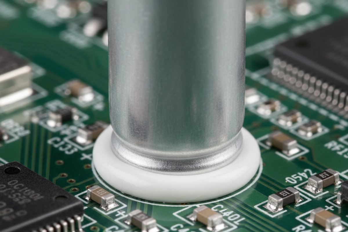
This is where “staking” enters the picture—applying structural adhesive to the base or sides of heavy components. This is the highest ROI activity for ruggedizing a board. By adding a fillet of adhesive (like a UV-cure acrylic or a high-viscosity silicone) to the perimeter of a heavy cap, you change the mechanics entirely. The vibration load transfers through the adhesive body to the FR4 laminate, rather than through the fragile copper leads.

There is often a knee-jerk reaction against silicone in industrial environments, a hangover from the days when acetic acid-curing silicones would corrode copper and volatile outgassing would foul relay contacts. Those fears are largely outdated. Modern neutral-cure, electronics-grade RTVs (Room Temperature Vulcanizing) and UV-cure staking materials are formulated specifically to avoid these issues. The risk of not using them—having a heavy capacitor shear off—is far higher than the risk of contamination, provided you choose the right material.
However, the glue is only as good as the surface preparation. You cannot simply squirt adhesive onto a dusty board and expect it to hold. In one instance involving solar inverters, a field failure rate spiked because the assembly house applied RTV directly over uncleaned no-clean flux residues. The silicone didn’t stick to the board; it stuck to the dirt on top of the board. Under vibration, the adhesive peeled away, and the capacitors broke free. A simple check of surface energy—using dyne pens or just rigorous process control—would have saved hundreds of thousands of dollars in warranty claims. The rule is simple: clean the spot where the glue goes, and ensure the adhesive creates a fillet that bridges the component body to the board surface. Never glue the leads themselves; glue the package.
The BGA Compromise: Corner Bonding
Ball Grid Arrays (BGAs) present a unique challenge. In mobile electronics (phones, tablets), the industry standard is Capillary Underfill (CUF)—a low-viscosity epoxy that flows underneath the entire chip, locking it to the board. This is great for drop protection, but it is a nightmare for industrial repair. If a BGA needs to be replaced, removing a fully underfilled chip usually results in ripped pads and a destroyed PCB.
For industrial gear, where the primary stress is thermal cycling and vibration rather than being dropped on a sidewalk, “corner bonding” (or edge bonding) is the superior strategy. Instead of filling the entire gap under the chip, you dispense a high-viscosity adhesive at the four corners of the BGA package. This locks the package to the board, preventing the solder balls from cracking during board flexure or vibration.
The beauty of corner bonding lies in its inspectability. With full underfill, you cannot see what is happening under the chip. You might have 30% voiding in the epoxy creating hotspots, and you would only know it if you did a destructive cross-section or an expensive X-ray analysis. With corner bonding, the center of the array remains open. Flux residues can outgas during reflow without getting trapped (a common cause of “popcorning” in underfilled parts). If the chip fails, a technician can cut the four corners of adhesive, reflow the part, and replace it without destroying the pads. You get 80% of the mechanical protection of underfill with 100% of the reworkability.
Chemistry as a Serviceability Feature
Once the mechanical heavy lifting is done with staking and bonding, you can address environmental protection with conformal coating. Here, the chemistry you choose dictates the serviceability of the product. Many engineers default to urethane coatings because they are tough and solvent-resistant. But ask yourself: do you want the coating to be solvent resistant?
If a board fails burn-in or needs a field repair, a urethane coating is an obstacle. It often requires harsh strippers or physical abrasion to remove, which damages components. Acrylic coatings (like Humiseal 1B31 or similar), on the other hand, are easily dissolved. A technician can take a solvent pen, dissolve the coating over a specific test point or component, perform the repair, and then recoat just that area.
We saw this play out at a contract manufacturer in Shenzhen, where a switch from urethane to acrylic turned a yield disaster into a manageable process. The rework technicians could solder directly through the acrylic coating if necessary (it smells terrible, but it works), or wipe it away in seconds. Yield recovery went from near zero to over 95%. Unless your device is going into an environment with specific chemical threats that dissolve acrylics (like fuel vapors or harsh cleaning agents), the serviceability of acrylics usually outweighs the durability of urethanes.
The Rework Simulation
Ruggedization looks like an engineering problem, but it’s actually an economic calculation. You must run a “Rework Simulation” in your head during the design phase. Imagine a technician with a standard soldering iron and a microscope trying to fix your board. Can they probe the test points? Can they replace the main MCU?
If the Bill of Materials (BOM) cost of the board is under $50, perhaps you don’t care. Pot it, seal it, and if it breaks, throw it in the shredder. But if that board costs $500 or $2,000, and it’s part of a critical industrial system, every barrier you place in front of the repair technician is a liability. By using staking for mass, corner bonding for BGAs, and reworkable coatings for the surface, you build a product that survives the field but doesn’t have to die there.


 Circuit Board Assembly")

