The regulatory ground has shifted. For years, leaded solder in ball grid array (BGA) packages enjoyed a reprieve under RoHS exemptions, justified by the immense technical challenges of transitioning high-reliability components to lead-free alternatives. That window is now closing. The exemptions that allowed tin-lead solder in BGAs for specific applications are expiring across major markets, forcing hardware teams into a lead-free migration. This is not a distant concern. The timelines are compressed, and the implications extend far beyond checking a compliance box.
The transition from leaded to lead-free BGAs is a reliability event, not a paperwork exercise. The fundamental material science has changed. Solder joint behavior under thermal and mechanical stress, the growth of intermetallics, the primary failure modes—all are different. Teams accustomed to the predictable, ductile performance of tin-lead eutectic solder must now navigate the harder, more brittle, and higher-temperature world of SAC alloys. The assumption that lead-free is a drop-in replacement is dangerously wrong and has already led to field failures where designers underestimated the shift.
The technical challenge is compounded by operational complexity. Supply chains must transition in lockstep with design. Rework and repair procedures require new temperature profiles and operator training. Validation testing timelines stretch because reliability data for leaded assemblies cannot simply be transferred. For products with multi-year qualification cycles in aerospace, medical, or automotive, the pressure is acute. A delay in starting the transition can cascade into missed certification windows and lost market access.
At Bester PCBA, we have guided teams through this transition across industries, and the pattern is consistent. Success hinges on a foundational understanding of the material differences, followed by a methodical plan that addresses design, supply, manufacturing, and validation in parallel. Teams that treat this as a minor substitution face costly redesigns and delayed launches. Those that approach it as a full-scale reliability engineering program navigate the transition with controlled risk.
The Exemption Window Is Closing
The original RoHS Directive banned lead in most electronics, but it carved out specific exemptions for applications where lead-free alternatives posed technical risks. Leaded solder in high-reliability BGAs fell squarely into this category, particularly for components in telecommunications infrastructure, medical devices, and industrial controls where solder joint integrity was mission-critical. The exemption acknowledged that lead-free alloys lacked the decades of field data that tin-lead offered.
Those exemptions are now expiring. The European Union has set clear end dates, with enforcement timelines that leave little runway for companies still designing with leaded components. Exemption 7(c)-I, for example, expired in 2021 for most categories. Other markets, including China, Japan, and South Korea, are following similar trajectories. While the timelines are staggered, the intent is convergent: the regulatory environment is tightening globally, and the technical justification for continued leaded use is evaporating.
The practical implication is a hard deadline. Products placed on the market after the exemption expires must be lead-free or face market access restrictions, fines, and supply chain rejection. For hardware teams, any product currently in development must factor in this transition. The clock is ticking.
Why Alloy Composition Is Not a Minor Detail
Faced with this deadline, the instinct is to treat the transition as a simple materials swap: replace the leaded BGA with a lead-free equivalent, tweak the reflow profile, and move on. This instinct has caused preventable failures in fielded products. The difference between tin-lead eutectic and lead-free SAC alloys is not a footnote in a datasheet; it is a fundamental shift in how solder joints form, respond to stress, and degrade over time.
Lead-free alloys—typically composed of tin, silver, and copper (SAC)—are harder, more brittle, and require higher reflow temperatures. This imposes additional thermal stress on the board, the component package, and all surrounding materials. The intermetallic compounds that form at the solder-to-pad interface grow faster and exhibit more brittle fracture characteristics. These are not edge cases; they are the central behaviors that determine whether a solder joint survives ten years in a harsh environment or fails in three.
The supply chain implications are just as immediate. Component manufacturers are phasing out leaded BGAs as demand shifts. Distributors are managing inventory transitions, making lead times for leaded parts unpredictable. Waiting until the last moment risks discovering your preferred component is no longer available in a leaded version, forcing an unplanned redesign under extreme time pressure.
Validation timelines introduce the final constraint. A product qualified with leaded solder cannot assume equivalent reliability without new testing. Accelerated life tests, thermal cycling, and vibration protocols must be repeated because the failure modes are not identical. For industries with stringent certification, this can mean six to twelve months of additional validation work. For teams that delay, the collision between this timeline and the market deadline becomes a crisis.
The Material Science of Lead-Free Solder Joints
The performance gap begins with the alloy itself. Tin-lead eutectic (63/37), the industry standard for decades, melts at 183°C and forms a ductile joint. Lead-free SAC alloys like SAC305 melt around 217°C. That 34-degree difference drives reflow peak temperatures into the 240-250°C range, translating to greater thermal stress on every material in the assembly.

Those higher temperatures punish the PCB substrate. Standard FR-4 laminates expand more, risking warpage and delamination, especially on boards with dense components or thick copper layers. The component package itself also endures higher stress. Molding compounds and die-attach materials are subjected to thermal excursions they may not have been designed for.
Higher Reflow Temperatures and Mechanical Stress
The temperature increase has direct mechanical consequences. Thermal expansion mismatches between the BGA package, the solder ball, and the PCB pad become more pronounced. Stresses that were manageable with tin-lead reflow can now generate enough force to crack solder joints or deform components. Large BGAs are especially vulnerable, as the outer rows of solder balls experience the highest mechanical strain during thermal cycling.
This constrains board material selection. High-temperature laminates often become necessary to handle the thermal load. Surface finishes must also be reconsidered, as common options like OSP can behave differently under lead-free profiles. Electroless nickel immersion gold (ENIG) remains a reliable option, but its thickness control becomes more critical to avoid brittle intermetallic formation. The thermal margin, once comfortable in a leaded process, shrinks. Designers must account for the reduced headroom between the reflow peak and the maximum rated temperature of sensitive components like oscillators or connectors.
Intermetallic Compound Formation and Long-Term Reliability
Intermetallic compounds (IMCs) form at the solder-copper interface during reflow, creating the metallurgical bond that makes a joint reliable. What matters is not their presence, but their composition, growth rate, and behavior over time. Lead-free solder produces different IMCs than tin-lead, and those differences are critical for long-term reliability.

In a tin-lead joint, the dominant IMC is a relatively ductile phase. In lead-free SAC joints, the same primary IMC forms, but its growth is accelerated by higher temperatures and the absence of lead, which acts as a growth inhibitor. A second, significantly more brittle IMC phase can also develop, particularly during high-temperature aging or multiple reflow cycles.
Thermal cycling accelerates this growth. Each temperature swing thickens the intermetallic layers, creating planes of weakness at the solder-pad interface. Under cyclic strain, cracks initiate and propagate through this brittle IMC layer rather than through the bulk solder. This failure mode, less common in tin-lead joints, means lead-free solder can exhibit shorter thermal fatigue life in harsh environments. For high-reliability products with 15- or 20-year field life expectations, this shift in failure distribution must be understood and validated.
Rework and Repair Realities Change
Rework is where the temperature increase becomes brutally tangible. Removing a leaded BGA could be done with peak temperatures around 220-230°C. Lead-free rework requires peaks near 260°C or higher to fully reflow SAC solder. That extra 30-40°C brings the assembly perilously close to the damage threshold for many board materials and adjacent components.
The risk of board damage skyrockets. Delamination and pad lifting become far more frequent, as the adhesion strength of copper pads degrades under prolonged high-temperature exposure. Once a pad lifts, the board is often scrap unless extensive jumper wire repairs are acceptable—a rarity in high-reliability applications.
Operator skill and equipment are now more critical. The margin for error is razor-thin; overheating causes damage, while underheating results in cold joints. Rework technicians trained on leaded processes need retraining, and older equipment may lack the thermal headroom or precision for reliable lead-free work. Field service adds another layer of complexity. Mixing leaded and lead-free solders is ill-advised, meaning service teams must either stockpile legacy leaded parts or qualify a full lead-free rework process for boards never designed to withstand it. Neither option is simple.
Building a Transition Plan That Holds
The transition to lead-free BGAs is a cross-functional program touching design, supply chain, manufacturing, and validation. Success demands the same rigor as a new product introduction.
Design and Component Selection
The design review must begin with thermal margin analysis. Can the board withstand higher reflow temperatures? Thermal simulation can identify at-risk areas, but if the existing stackup is insufficient, a redesign with higher-Tg laminates may be necessary. Component selection must prioritize parts with robust lead-free pedigrees and proven reliability data. Not all lead-free BGAs are created equal. Finally, the combination of board pad finish and BGA ball alloy must be confirmed through testing, not assumptions.
Supply Chain Coordination and Inventory Strategy
Engage suppliers early. They need visibility into your transition timeline to manage their inventory and production. Lead times for lead-free components may differ, and securing supply commitments is crucial to prevent last-minute shortages. Dual sourcing becomes more complex, as it may require requalifying both suppliers with their lead-free offerings. Inventory timing is a balancing act between ordering a last-time-buy of leaded parts—risking obsolete stock—and ordering too little, risking a line-down situation.
Manufacturing Process Qualification

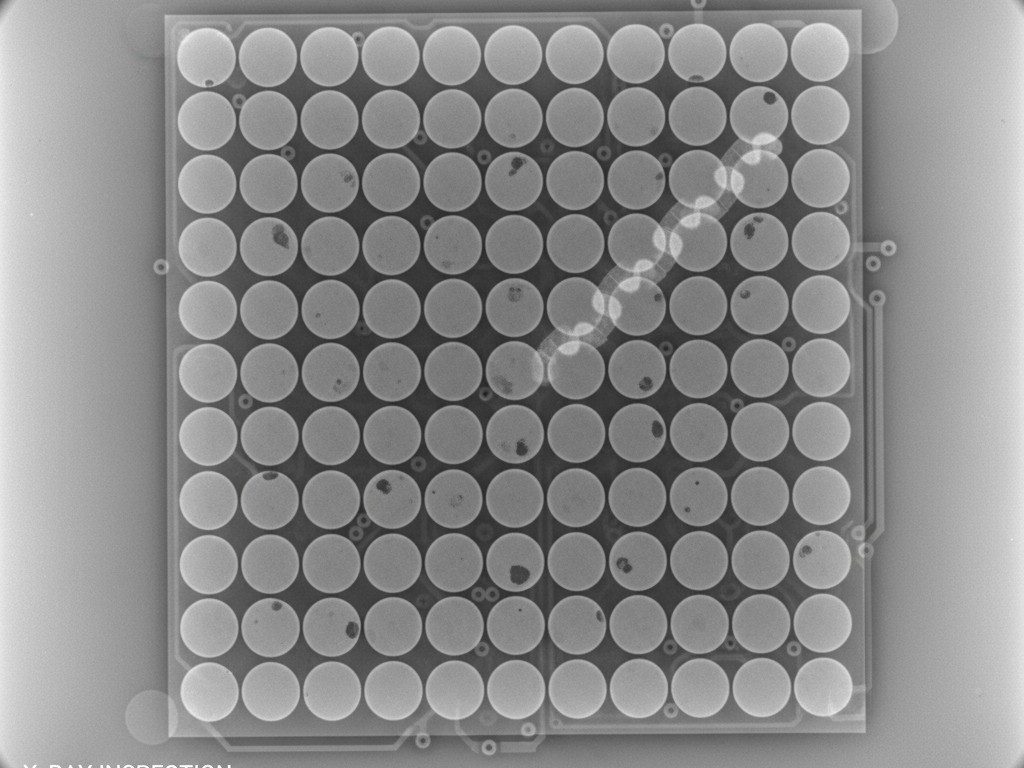
Reflow profile development is the first task. The profile must be optimized for the specific SAC alloy and the thermal mass of the board, using thermocouples on actual assemblies to verify temperatures at critical locations. Inspection criteria must also change. X-ray and automated optical inspection (AOI) systems need to be recalibrated, as the appearance of an acceptable lead-free joint differs from a leaded one. A first-article build, complete with destructive physical analysis, is non-negotiable to tune the process before committing to volume production.
Validation Testing You Cannot Defer
Existing qualification data for a leaded product does not transfer to a lead-free version. The material properties, failure modes, and degradation mechanisms are all different. Reliability testing must be repeated.

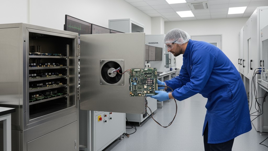
The required tests depend on the application, but thermal cycling is nearly universal. Following guidelines like IPC-9701, assemblies are subjected to hundreds or thousands of temperature cycles chosen to represent the expected field environment. Vibration and mechanical shock testing are critical for products in dynamic environments, as the brittle nature of lead-free solder makes it respond differently to mechanical stress. Highly accelerated life testing (HALT) can also be used to rapidly find the new weakest links in the design.
For products in medical, aerospace, or automotive, this validation and certification process can take a year or more. Starting this process only after a deadline is announced leaves no buffer for failures or redesigns. Deferring validation because a product “seems to work” is a gamble with field reliability and market access.
Managing Legacy Products and Mixed Inventory
Products already in the field present a unique challenge. Servicing systems that used leaded BGAs requires a plan for replacement components. Once leaded parts are no longer manufactured, you must either rely on a carefully calculated stockpile or qualify a risky lead-free rework process for legacy boards.
In manufacturing and service depots, strict inventory segregation is essential to prevent accidental mixing of leaded and lead-free parts. A mismatched component can create an assembly with unpredictable behavior and reliability. Clear labeling and process controls are required to maintain traceability.
Finally, the phase-out must be coordinated with the product lifecycle. For a product nearing its end-of-life, a last-time-buy of leaded components may be the pragmatic choice. But for any product with years of life remaining, the transition is unavoidable. Delaying only compresses the timeline and multiplies the risk.
The end of RoHS exemptions for leaded BGAs is not a minor regulatory update. It is a forcing function that will expose weaknesses in design, supply chain resilience, and process control. The teams that start early, treat the transition as a reliability engineering program, and validate their assumptions with hard data will navigate the change. Those that wait will find themselves reacting, making decisions under pressure with incomplete information. The timeline is set. The choice is how to use it.


