What is Controlled Impedance
Controlled impedance refers to the management and control of the resistance that a signal trace exerts on a signal that involves designing and implementing specific impedance values for the signal traces on a circuit board to ensure optimal signal integrity and minimize signal degradation.
Impedance is the opposition to the flow of AC in a circuit and is measured in Ohms. In high-speed digital, analog, RF, and microwave applications, maintaining consistent impedance throughout the PCB is crucial to minimize signal reflections, distortions, and losses, which can degrade overall performance.
To achieve controlled impedance, select the appropriate substrate material with the desired dielectric constant and loss tangent, calculate the trace dimensions (such as width and spacing) based on the desired impedance, and carefully place the traces in specific locations on the PCB.
The substrate material determines the impedance characteristics of the traces. By considering the material properties, designers can calculate the required trace dimensions to achieve the desired impedance. Common impedance values in the PCB industry include 50 ohms and 75 ohms, although other values may be used depending on the design requirements.
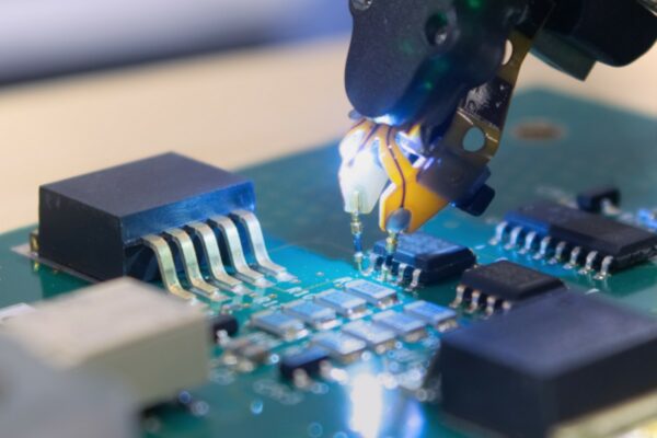
Controlled impedance boards provide repeatable high-frequency performance, ensuring consistent signal timing and reliable transmission. Manufacturing processes such as controlled etching, plating, and layer stack-up are employed to meet the specified impedance requirements. Impedance testing and validation techniques, such as time domain reflectometry (TDR) or network analyzers, are used to verify the impedance values of the fabricated PCBs.


