There is a specific silence that falls over a production floor when a 50,000-unit run grinds to a halt. It isn’t a software bug or a component shortage. It’s a “banjo string”—a harness routed so tightly across a hinge point that it looks perfect in the model but snaps the solder pads off the board in the real world.
In the CAD environment, the cable was a compliant, zero-mass cylinder that followed a spline curve obediently. On the assembly line, that same bundle of wires is a stiff mechanical spring under tension. The operator had to force the connector into the header, pre-loading the joint with just enough stress that the first vibration test shattered the connection.
This disconnect between the digital twin and physical reality is where most box build integrations fail. We treat wires as if they are merely electrical conduits—lines on a schematic that happen to need a physical path. But once you move from a bench prototype to a mass-produced enclosure, a wire is no longer just a conductor. It is a mechanical component with mass, stiffness, bend radius limits, and a nasty habit of work hardening. If the routing strategy is an afterthought left for the final week of design, the result is almost always a frantic retrofit, a pile of rejected units, or worse—a field failure six months later when the insulation finally rubs through.
The Physics of the “Ghost” Wire
The fundamental error lies in trusting the simulation of flexible materials. CAD software is excellent at managing rigid bodies—aluminum enclosures, PCB standoffs, and heat sinks don’t change shape when you pick them up. Wires do. When you route a bundle of six 18AWG conductors in a 3D model, the software allows you to turn a sharp 90-degree corner instantly. It assumes the material has no memory. In reality, that bundle fights to straighten itself out, exerting constant, low-level torque on whatever it terminates to.
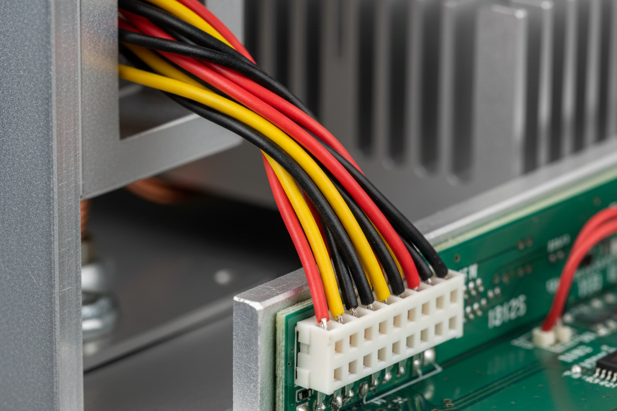
If that termination is a surface-mount header like a JST PH or a Molex Micro-Fit, that torque transfers directly to the solder joints. Copper work hardens when manipulated. Every time a technician bends that cable to fit it into the box, the wire becomes stiffer and more brittle. If the design doesn’t account for a “service loop”—extra slack that allows the wire to relax—the tension will eventually win. The solder will crack, or the header will lift off the pads entirely.
Designers are often tempted to solve this by ordering custom-length cables cut to the exact millimeter to keep the box looking “clean.” During the New Product Introduction (NPI) phase, this is usually a mistake. A custom cable with zero slack requires zero tolerance in assembly. If the assembler routes it slightly differently, or if the vendor cuts it 5mm short, the cable becomes a structural tension member. It is far safer, and often cheaper, to use standard lengths with a planned service loop to absorb these variances. You want a relaxed fit, not a tight drum skin.

The rule of thumb for reliability is simple: the cable should never pull on the connector. The strain relief must happen before the termination. If you unplug the connector and the wire springs back two inches, you have designed a failure mechanism.
The Knuckle Test
Beyond the physics of the wire itself, you have to account for the physics of the human hand installing it. We often see enclosures designed with connectors tucked deep under a lip or buried between a heat sink and a sidewall. The designer, working with a mouse and scroll wheel, can easily zoom in, rotate the view, and click the mate command. A field service technician, standing on a ladder in a dimly lit server room, doesn’t have that luxury.

Visualize a technician wearing size Large safety gloves. Can they reach the deepest connector in the chassis without their knuckles grazing a sharp PCB edge or a high-voltage capacitor? If they have to use needle-nose pliers to grip the connector housing because their fingers don’t fit, the design has failed. Pliers crush plastic housings. They slip and gouge insulation. If a tool is required to unplug a standard internal connector, it’s not a serviceable design; it’s a liability.
We saw this in a recall for a handheld diagnostic tool where the battery connector was buried so deep that technicians were pulling on the wires to disconnect it. The crimps held for the first few cycles, but eventually, the wire strands fatigued and snapped inside the insulation. The unit would power on intermittently, leading to hours of troubleshooting for a problem invisible to the naked eye. The fix wasn’t a better crimp; it was moving the connector ten millimeters to the left so a human thumb could reach the latch.
Entropy and Anchors
If you do not explicitly define where a cable goes, gravity and vibration will decide for you. This is the principle of deterministic routing. A harness allowed to float will eventually settle against the hottest component in the box or chafe against the sharpest edge of the chassis.
The most common failure in low-volume builds is relying on adhesive-backed cable tie mounts. They are fast, cheap, and look professional on day one. But inside an industrial enclosure, temperatures fluctuate. The adhesive cycles, dries out, and eventually fails. Two years later, the mount falls off, and the harness drops onto a fan blade or a high-voltage rail. For any equipment expected to last more than a warranty period, mechanical fastening is mandatory. This means screw-mount P-clips, saddle clamps, or rigid wire ducts like those from Panduit.
Adhesives have their place, but rarely in structural holding. We often see prototypes held together with hot glue or blobs of RTV silicone. This is the hallmark of an amateur mindset. Hot glue does not bond reliably to smooth connector housings, and standard RTV releases acetic acid that can corrode contacts. If you are tempted to use a glue gun to fix a routing problem, stop. You need a mechanical constraint—a molded channel, a clip, or a zip tie anchored to a chassis point.
Even with proper anchors, you must respect the “crush” risk. A zip tie gun set to high tension can crush the insulation of a 26AWG signal wire, causing a short to the shielding or simply cutting the data stream. We often have to retrofit designs with “pinch point” protection—custom Kapton shields or spiral wrap—because the enclosure clamshell was designed without a dedicated channel for the wires. When the case was screwed shut, the wires were pinched in the seam. If the routing isn’t deterministic—if there isn’t a specific channel forcing the wire into a safe zone—it isn’t a design. It’s a wish.
The Cost of the Field Call
It is easy to look at a $0.05 P-clip or a slightly larger enclosure and argue for cost reduction. “Air is free,” the argument goes, “why are we paying for a bigger box?” But the calculation changes immediately when you factor in the cost of a single field failure.
Sending a technician to a customer site to replace a control unit because a $0.10 connector rattled loose costs anywhere from $500 to $5,000, depending on the industry. That single service call wipes out the cost savings of skimping on strain relief for the entire production run. The reputational damage—the perception that the product is “flaky”—costs even more.
Routing isn’t an aesthetic choice. It’s not about making the inside of the box look like a gaming PC with combed cables and RGB sleeving. It is a reliability discipline intended to ensure the electrical connection survives the brutal reality of thermal expansion, vibration, and human handling. If the harness is an afterthought, the product is a prototype. Real production integration starts with the wire.


