PCB soldering is a skill that’s both an art and a science. This guide will take you on a journey from understanding the basics of PCB soldering, to exploring the essential tools and materials you’ll need and diving into the various soldering techniques. We’ll walk you through the step-by-step process of soldering a PCB, share some insider tips and tricks, and help you navigate common soldering problems. And for those ready to take their skills to the next level, we’ll delve into advanced soldering techniques. Whether you’re a hobbyist or a professional, this article is your roadmap to mastering PCB soldering.
What is PCB Soldering
PCB soldering is an essential process in the electronics field, which involves the use of heat to melt a metal alloy, commonly known as solder, to establish a conductive joint between electronic components and the printed circuit board. This joint not only physically secures the components to the board but also forms an electrical connection between them, ensuring a seamless progression of the electronic signal.
The solder used in this process is typically a blend of tin and other elements such as lead, silver, or brass. Yet, due to health and environmental considerations, lead-free solder, which is a combination of tin, copper, and silver, is gaining popularity. This solder is designed to have a low melting point, enabling it to melt and cool rapidly, forming a solid, conductive bridge when it cools and solidifies.
Mastering PCB soldering is a valuable skill in electronics, used in a wide array of applications from assembling intricate computer motherboards to repairing straightforward electronic toys. It demands precision, patience, and a steady hand, as the components involved are often minuscule and delicate, and a poorly soldered joint can lead to circuit failure.
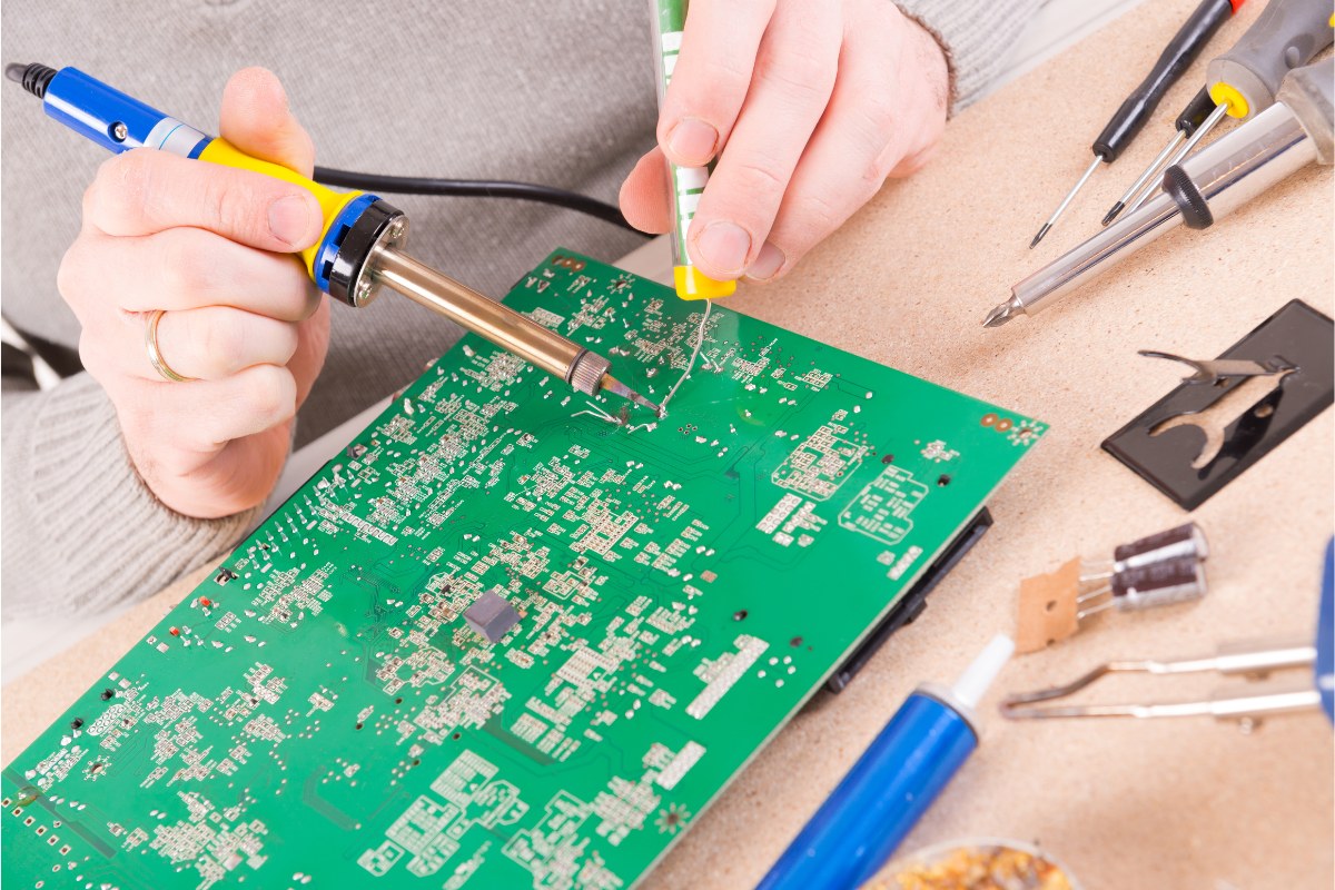
There are two primary methods of PCB soldering: manual soldering and reflow soldering. Manual soldering is performed by hand using a soldering iron, a tool that resembles a pen and heats up to melt the solder. This method is typically used for small-scale projects or repairs. Conversely, reflow soldering involves applying solder paste to the PCB, placing the components on top, and then heating the entire assembly in a specialized oven. This method is commonly used in mass production due to its speed and consistency.
Tools and Materials for Soldering
Soldering a PCB is a precision task, and the quality of your tools and materials can significantly influence the outcome. The primary tools and materials for soldering include a soldering iron, solder wire, and solder flux, each playing a unique role in the process.
The soldering iron, often referred to as a soldering gun, is the cornerstone of the soldering process. It consists of three main components: the handle, the element, and the bit or tip. The element functions similarly to an electric heater, producing heat when electricity flows through it. This heat is then transferred to the soldering junction via the iron piece. While standalone soldering irons are common, soldering and desoldering rework stations are often used in repair shops, factories, and laboratories for their efficiency and ability to perform more complex tasks.
Solder wire is a fusible metal alloy that creates a permanent bond between electronic parts. The most common form used in electronics manufacturing is an alloy containing 60% tin and 40% lead, which has a melting point of 190 degrees Celsius. It comes in various gauges, with thinner gauges preferred over thicker ones. An 18 or 22 gauge solder wire is a suitable choice for general applications.
Solder flux, often referred to as solder paste, is a chemical cleaning agent that facilitates the soldering process. It removes the oxide coating on the surface of solderable metals and enhances the solder’s wetting ability. Modern solder wires often have flux in the center core, eliminating the need for separate flux.
In addition to these primary tools and materials, other soldering accessories can enhance the soldering process. These include a soldering gun stand, a cutter, a desoldering pump, and safety equipment like goggles and gloves. It’s also beneficial to have a soldering iron holder and cleaning sponge for safe storage and maintenance of the soldering iron.
Moreover, if you’re going to be soldering frequently, having a heat source that can reach 600-800 degrees Fahrenheit, an exhaust fan to vent fumes, and “third hands” or “helping hands” to hold your work can be extremely helpful.
The quality of your soldering project is directly influenced by the quality of your tools and materials. Therefore, investing in high-quality soldering tools and materials is a wise decision. In the following sections, we will delve deeper into each of these tools and materials, discussing their specific roles, types, and selection criteria.
Soldering Iron
A soldering iron, often compared to a pencil due to its shape, is the fundamental tool in any soldering operation. This handheld device transforms electrical energy into heat, which is then utilized to melt the solder wire, allowing it to flow into the joint between two workpieces.
The soldering iron consists of three primary components: the handle, the heating element, and the bit or tip. The handle is typically designed with a padded grip for comfort and insulation, safeguarding the user from the heat. The heating element, akin to that of an electric heater, generates heat when electricity flows through it. This heat is then transferred to the bit or tip, which is usually crafted from copper plates and is the point of contact with the solder and the PCB.
There’s a variety of soldering irons, each with its unique benefits. Pencil irons are the simplest and are ideal for beginners due to their straightforwardness and cost-effectiveness. Yet, they lack temperature control, which can be a limitation for more intricate projects. Soldering stations, in contrast, offer temperature control and are more suited for advanced tasks. They come with a base station that allows for precise temperature adjustments. Cordless irons are battery-powered and offer the advantage of portability, making them ideal for tasks where access to a power outlet is limited.
In professional settings like repair shops, factories, and laboratories, soldering and desoldering rework stations are often employed. These systems offer greater efficiencies and can perform more complex tasks than individual, single-function equipment.
When selecting a soldering iron, consider its wattage, tip compatibility, temperature control, and comfort and safety features. A soldering iron with a power output of 20-60 watts is usually sufficient for most PCB soldering tasks. The tip of the soldering iron should be replaceable and compatible with the types of tips you plan to use. Adjustable temperature control is crucial for working with different types of components and solder. Lastly, look for a lightweight iron with an ergonomic handle and safety features like a heat-resistant handle and a stand for resting the hot iron when not in use.
Solder Wire
Solder wire, a vital component in the soldering process, serves as the binding agent that establishes a durable connection between metal workpieces. It’s typically a fusible metal alloy, with the most prevalent variant being an alloy containing 60% tin and 40% lead. This specific alloy has a melting point of 190 degrees Celsius and solidifies upon cooling. Yet, due to health and environmental considerations, lead-free alternatives, often a blend of tin, silver, and copper, are gaining popularity.
When selecting solder wire, consider these crucial factors:
Diameter
Solder wire is available in a variety of diameters, from 0.020 inches to 0.062 inches. The appropriate diameter hinges on the size of the components you’re soldering. For smaller, delicate components, a thinner wire, such as 18 or 22 gauge, offers more control and minimizes the risk of applying excessive solder. For larger components, a thicker wire may be more efficient.
Flux Core
The majority of solder wires feature a flux core, which cleans the metal surfaces and enhances solder flow. The flux core can be rosin-based, leaving minimal residue and typically not requiring post-soldering cleaning, or water-soluble, which is more aggressive and necessitates cleaning after soldering.
Lead vs. Lead-Free
Traditional solder wire is a lead-tin mix. But, many now opt for lead-free solder wire due to health and environmental considerations. Lead-free solder, often a tin, silver, and copper blend, requires a higher melting temperature and can be slightly more challenging to handle.
Melting Point
The solder wire’s melting point is crucial. A lower melting point allows the solder to flow more easily, but it may also be less robust. A higher melting point yields a stronger bond but requires a higher temperature and can be more difficult to manage.
The ideal solder wire for your project hinges on the specific task requirements. Always consider your project’s nature and the materials you’re working with before selecting your solder wire.
Solder Flux
Solder flux, or solder paste is responsible for removing oxidation from the surfaces of the metals that are to be joined. It enhances the wetting properties of the molten solder and prevents further oxidation during the soldering process.
Flux is specifically designed to eliminate the oxide coating on the surface of solderable metals, thereby improving the solder’s ability to wet the surface. This is crucial because a clean metal surface is necessary for the solder to form a strong bond. Moreover, the quality of soldering, which is significantly influenced by the flux, can determine the longevity of the soldering.
There are three primary types of solder flux: rosin flux, water-soluble flux, and no-clean flux. Each type has its unique characteristics and applications, and understanding these can help you select the right flux for your soldering project.
Rosin Flux
This is the most common type of flux used in electronics soldering. It’s derived from natural rosin, a type of resin from pine trees. Rosin flux is non-corrosive and non-conductive, making it safe for electronic components. Yet, it leaves a sticky residue after soldering that needs to be cleaned off.
Water-Soluble Flux
This type of flux can be cleaned off with water after soldering. It’s more aggressive than rosin flux, making it suitable for soldering metals that are more difficult to solder, like copper and brass. But, it’s also more corrosive and can damage sensitive electronic components if not thoroughly cleaned off after soldering.
No-Clean Flux
This is a type of flux that doesn’t leave a residue that needs to be cleaned off after soldering. It’s less aggressive than water-soluble flux but more so than rosin flux. It’s a good choice for applications where post-soldering cleaning is difficult or undesirable.
Modern solder wire often has flux in the center core, eliminating the need for separate flux. When choosing a solder flux, consider the type of metal you’re soldering, the sensitivity of the components, and whether you can clean the flux residue after soldering. Remember, the purpose of flux is to ensure a clean metal surface for the solder to bond with, so choose a flux that will effectively clean your specific metal without damaging your components.
Types of Soldering Techniques
Soldering techniques are crucial for establishing robust and efficient connections in PCBs. These techniques are broadly divided into two categories: soft soldering and hard soldering.
The choice between soft and hard soldering hinges on the materials you’re working with, the strength of the joint required, and the heat tolerance of the components. It’s also vital to note that there are different methods to execute the PCB soldering process, such as hand soldering, reflow soldering, and wave soldering. Each method has its own advantages and is suitable for different types of soldering requirements.
Soft Soldering
Soft soldering is a widely utilized technique in electronics and plumbing, primarily used to establish electrical connections and secure electronic components to PCBs. This method is particularly effective for low-temperature applications, typically involving a filler metal or solder with a melting point below 400 degrees Celsius (752°F). Despite its reliability in creating electrical connections, it doesn’t offer the same level of bonding strength as hard soldering.
The process commences with the preparation of the surfaces to be soldered. These surfaces must be immaculate and free from any oxidation, which can be achieved using fine abrasive paper or a specialized cleaning solution. A clean surface is a prerequisite for a robust and reliable solder joint.
Following surface preparation, flux is applied. Flux, a chemical cleaning agent, plays a pivotal role in removing oxidation and promoting solder flow. It ensures the solder bonds properly with the surfaces, a critical aspect of soft soldering.
The subsequent step involves heating the joint using a soldering iron, which could be electric or gas-powered. The objective is to heat the joint, not the solder. Therefore, the solder should be applied to the joint, not directly to the iron. If the joint is adequately heated, the solder will melt and flow into it.
Once the solder has flowed into the joint, the heat source is removed, and the joint is allowed to cool naturally. It’s crucial not to disturb the joint during cooling as it can lead to a weak or brittle solder joint.
Soft soldering typically employs a tin-lead alloy as a filler metal. This alloy, with a melting point greater than 400 °C or 752°F, acts as a binding agent between the component and the board. A gas torch is often used to generate the necessary heat for this project, causing the alloy to melt and bind the component to the board.
While soft soldering is a versatile technique suitable for a wide range of applications, it’s not as robust as hard soldering. Therefore, it’s not recommended for joints that will be subjected to high stress or high temperatures. Yet, for most electronics projects, soft soldering is the preferred technique. It’s relatively easy to master, and with some practice, you can achieve professional-quality results.
Hard Soldering
Hard soldering, often referred to as silver soldering or brazing, is a technique employed to fuse two different metal surfaces. This process doesn’t directly melt the solder, but heats the base metals to a temperature that causes the solder to melt instantly. Once cooled, a remarkably robust joint is formed due to the “capillary effect.”
The solder used in hard soldering is typically composed of silver or brass, and it requires a higher melting point than soft solder. This necessitates the use of a blowtorch to generate the required heat. Hard soldering is commonly used to join pieces of brass, copper, silver, or gold.
The process of hard soldering involves spreading the solder throughout the holes of the components. These holes open up when exposed to high temperatures, allowing the solder to flow into them. It’s crucial to thoroughly clean the surfaces before starting the process to remove any traces of grease that could interfere with the soldering.
Hard soldering can be further divided into two sub-processes: silver soldering and brazing. Silver soldering uses a silver alloy, often cadmium-silver, as a space-filling metal. This method is used to fabricate small components and perform certain types of maintenance on a circuit board. The silver offers a free-running characteristic, although it’s not typically the best choice for space filling on its own. That’s why another flux is usually used to create reliable silver soldering.
On the other hand, brazing is a technique used to connect two terminals made of base metals using a liquid filler metal, typically brass. The result is a robust joint that connects the two different terminals.
Here’s a simple guide on how to perform hard soldering:
- Preparation: Thoroughly clean the surfaces of the metals you want to join. Any dirt, grease, or oxidation can prevent the solder from bonding properly. You can use a wire brush or sandpaper to clean the surfaces.
- Apply Flux: Apply a thin layer of flux to the areas you want to join. Flux is a chemical cleaning agent that helps the solder flow and bond to the metal.
- Heat the Joint: Use the torch to heat the joint evenly. The goal is to get the entire joint up to the temperature where the solder will flow, not just one spot.
- Apply the Solder: Touch the end of the solder wire to the joint. The heat from the joint should be enough to melt the solder. If it’s not, you can use the torch to gently heat the solder.
- Let it Cool: Once the solder has flowed into the joint, remove the heat and let the joint cool naturally. Don’t move the joint until it has cooled completely, as this could weaken the bond.
- Clean the Joint: After the joint has cooled, clean off any excess flux with warm water and a brush.
Steps to Soldering a PCB
Soldering a PCB is a meticulous process that demands precision and attention to detail. Here are the steps to guide you through the process:
Soldering Iron Preparation
Initiate by tinning your soldering iron. Tinning is a process that involves coating the iron’s tip with solder, which aids in heat transfer and protects the tip from wear and tear. Allow your iron to heat up to the appropriate temperature, typically around 350°C for lead-based solder and 375°C for lead-free solder. Once the iron is hot, wipe the tip on a wet sponge to ensure it’s clean. After it’s clean, dip the iron tip in the solder, ensuring it’s completely coated.
PCB Preparation
Clean your PCB with an industrial cleaning wipe or acetone cleaner to remove any dust or other debris that may affect your soldering. Compressed air can also be used to remove small particles and dry the surface quickly.
Flux Application
Apply a thin layer of flux to the area you’re going to solder. Flux helps the solder flow and bond to the metal surfaces, and it also reduces oxidation.
Component Positioning
Place the components you’re soldering onto the PCB. Make sure the leads of the component go through the correct holes on the board. If the components don’t stay in place, you can bend the leads slightly under the board so they hold still.
Joint Heating
With a small amount of solder on the iron’s tip, touch the tip to the component lead and board. Connecting the tip with both these pieces is critical to ensure the solder sticks them together and heats them properly. Only hold the iron on the joint for a few seconds, as overheating the joint can cause bubbling.
Solder Application
The solder should be applied directly to the heated joint. If it’s been heated thoroughly and correctly, the hot joint will be enough to melt the solder and begin to flow freely. Continue touching the solder strand to the joint until a small mound has formed.
Cooling and Trimming
Set the solder strand and iron aside, and allow the joint to cool. While it cools, it’s essential to keep the surface flat and still, as moving it will result in a grainy, dull finish. After the joint cools, visually inspect it to ensure it looks adequate. Once you’re satisfied with the soldered joint, trim the lead and extra wire just above the joint.
PCB Cleaning
After soldering the components, clean off any excess flux that’s spread onto the PCB with a cleaning chemical, like isopropanol.
Tips and Tricks for Soldering
Soldering is a skill that improves with practice and the application of the right techniques. Here are some expert insights to help you achieve superior results when soldering a PCB:
Preparation is Essential
Prior to soldering, ensure that the PCB and the components you’re going to solder are clean. Any dirt, grease, or oxidation can hinder the solder from adhering properly. Use isopropyl alcohol and a soft brush to clean the surfaces.
Select the Appropriate Solder
Not all solder is the same. For most electronics work, a rosin-core solder is recommended. The rosin core acts as a flux, aiding the solder to flow and bond to the metal parts. The thickness of the solder wire also matters. For delicate work, opt for a thinner solder wire.
Correct Iron Temperature
The temperature of your soldering iron is crucial. If it’s too hot, you risk damaging the PCB or the components. If it’s too cold, the solder won’t melt properly. A good starting point is around 350°C (662°F), but you may need to adjust depending on the specific solder and components you’re working with.
Tinning the Tip
Always apply a small amount of solder to the tip of your soldering iron before you start soldering. This process, known as tinning, improves heat transfer from the iron to the joint and also prolongs the life of the tip.
Heat the Joint, Not the Solder
Apply the heat to the joint you want to solder, not directly to the solder wire. Once the joint is hot enough, touch the solder to the joint, not the iron. This ensures that the solder flows properly into the joint.
Avoid Moving the Joint
Once you’ve applied the solder, don’t move the joint until the solder has completely cooled and solidified. Moving the joint while the solder is still liquid can result in a weak joint, known as a ‘cold solder joint’.
Utilize Heatsinks
Heatsinks are essential for the leads of sensitive components such as ICs and transistors. They help to dissipate heat and protect the component from damage. If you don’t have a clip-on heatsink, a pair of pliers can serve as a good substitute.
Maintain a Clean Iron Tip
A clean iron tip means better heat conduction and a better joint. Use a wet sponge or brass wire wool to clean the tip between joints.
Double Check Joints
After soldering, it’s good practice to check the joints. Use a magnifying glass to visually inspect the joint and a meter to check resistance.
Solder Small Parts First
Solder resistors, jumper leads, diodes, and other small parts before you solder larger parts like capacitors and transistors. This makes assembly much easier.
Install Sensitive Components Last
Install CMOS ICs, MOSFETs, and other static sensitive components last to avoid damaging them during assembly of other parts.
Ensure Adequate Ventilation
Most soldering fluxes should not be breathed in. Avoid breathing the smoke created and ensure that the area you are working in has adequate airflow to prevent the buildup of noxious fumes.
Practice is Key
Start with some scrap components and PCBs before moving on to your actual project. This will help you get a feel for how the solder flows and how much heat is needed.
Common Soldering Problems to Avoid
Soldering a PCB can be a complex task, and it’s not unusual to face a few challenges along the way. Here are some common soldering issues you might encounter and how to sidestep them.
Cold Solder Joint
This arises when the solder doesn’t fully melt, resulting in a weak and unreliable connection. It often appears dull or grainy. To sidestep this, ensure your soldering iron is sufficiently hot (around 350-400 degrees Celsius) and the joint is adequately heated before applying the solder.
Bridging
This happens when solder flows between two or more adjacent pins, creating an unintended connection. To prevent bridging, use a fine-tip soldering iron for precision and apply just enough solder to cover the joint, not the pins.
Overheating Components
Overheating can damage the PCB or the components. Avoid holding the soldering iron on the PCB for too long. If a joint is taking too long to solder, remove the heat and let it cool down before trying again.
Insufficient Wetting
This happens when the solder doesn’t spread out on the pad or component lead, indicating a poor connection. To avoid this, ensure the surface is clean and free of oxidation. Applying a bit of flux can also help the solder flow better.
Solder Balls
These are tiny spheres of solder splatter that can cause short circuits. They often occur when the soldering iron is too hot or the solder wire is removed too quickly. Maintain a steady hand and work at a controlled pace to prevent this.
Oxidation
Over time, the tip of your soldering iron can oxidize, reducing its heat transfer ability. Regularly clean and tin your soldering iron tip to keep it in good working condition.
Excessive Soldering
Applying too much solder can create bubbles at the joint, potentially leading to errors. Apply just enough solder to wet the pad and the pin during soldering.
Component Shifting
Misalignment of components on the PCB can occur when components float on melting and floating solder, causing them to settle in the wrong areas. Ensure components are correctly placed before soldering.
Lifted Pads
This problem often occurs when you utilize little solder. High force on components can cause them to lift, potentially damaging the board or causing a short circuit.
Solder Starved Joints
These are joints that do not have enough solder, leading to a weak electrical contact. Apply sufficient heat to the lead to avoid this issue.
Solder Splashes
These occur when excessive flux is applied or inadequate preheating is done, leading to solder bits sticking onto solder masks in splatters. Ensure the PCB surface is clean before soldering to prevent this.
Pin Holes and Blow Holes
These problems usually arise during wave soldering, and they appear as holes in solder joints. These holes form when excess moisture buildup in your board tries to escape through thin copper plating. Preheat the boards to ensure that the moisture contained in it escapes as vapor.
Safety Measures When Soldering
Soldering, a process involving high temperatures and potentially hazardous materials, necessitates a strong emphasis on safety. Here are some indispensable safety measures to adhere to when soldering a PCB:
Don Protective Gear
Shield your eyes from solder splatter or flux particles with safety glasses. Heat-resistant gloves can also safeguard your hands from accidental burns.
Ensure Adequate Ventilation
Soldering generates fumes that can be harmful when inhaled. It’s crucial to either work in a well-ventilated area or employ a fume extractor to eliminate these fumes from your workspace.
Maintain an Organized Workspace
A cluttered workspace can be a recipe for accidents. Always place your soldering iron in a stand when not in use and keep all flammable materials, such as alcohol, at a safe distance from the work area.
Exercise Caution with the Soldering Iron
The soldering iron should always be held by the handle, never the metal part. Remember, the iron can stay hot for a while even after it’s switched off, so allow it to cool before changing tips.
Avoid Direct Contact with the Solder Joint
The solder joint can remain hot for some time post-soldering. Refrain from touching it immediately after soldering to prevent burns.
Opt for Lead-Free Solder When Possible
Lead-based solder can be toxic, so it’s safer to opt for lead-free solder if possible.
Practice Good Hygiene After Soldering
Once you finish soldering, wash your hands thoroughly. This is particularly vital if you’re using lead-based solder, but it’s a good practice even with lead-free solder to remove any residual flux.
Dispose of Solder Waste Responsibly
Any waste materials, like used solder or flux, should be disposed of in a safe and environmentally friendly manner.
Secure Loose Hair and Sleeves
Loose hair and clothing can pose a fire risk or interfere with your work. Ensure they are secured before you start soldering.
Advanced Soldering Techniques
In PCB soldering, several advanced techniques can significantly enhance the quality of your work and the efficiency of your process. These techniques are typically employed by experienced solderers who have mastered the basics and are looking to elevate their skills. Let’s delve into some of these advanced soldering techniques.
Surface Mount Soldering (SMT)
This technique involves soldering components designed to be mounted directly onto the PCB’s surface, rather than through holes. SMT requires precision and a steady hand, as the components are often quite small. The process typically involves applying solder paste to the PCB, placing the components on top, and then heating the entire assembly to melt the solder and create the necessary electrical connections.
Reflow Soldering
This common method used in SMT involves applying solder paste to the PCB, placing the components on top, and then heating the entire assembly in a reflow oven. The heat causes the solder paste to melt and flow, creating a solid connection between the component and the PCB. This technique is particularly useful for soldering a large number of components simultaneously.
Hot Air Soldering
This technique uses a hot air gun to melt the solder. It’s particularly useful for reworking or repairing PCBs, as it allows you to target specific components without affecting others. The hot air gun can also be used to remove components from a PCB by melting the solder that holds them in place.
Wave Soldering
This bulk soldering method involves passing the PCB over a wave of molten solder. The solder adheres to the areas where it’s needed, creating a solid connection. This technique is typically used in mass production settings, where a large number of PCBs need to be soldered quickly and efficiently.
Selective Soldering
This technique is used when only specific parts of the PCB need to be soldered. It involves using a machine to precisely apply solder to certain areas, while avoiding others. This is particularly useful for PCBs that have a mix of surface mount and through-hole components.
BGA Soldering
Ball Grid Array (BGA) is a type of surface mount packaging used for integrated circuits. BGA soldering involves placing the BGA component on the PCB, applying heat to melt the solder balls underneath the component, and then allowing it to cool to create a solid connection. This technique requires a high level of precision and is typically done using specialized equipment.
Advanced PTH Techniques
These techniques include using flux, removing solder jumpers, and desoldering components. Desoldering can often be the best way to learn how to solder. There are many reasons to desolder a part: repair, upgrade, salvage, etc. Many of the techniques used in the video aid in the desoldering process. There is another method of removing solder from through-holes that we refer to as the slap method.


 Circuit Board Assembly")

 PCB Technology: Types, Benefits, Challenges, and Applications")