Protecting a PCBA in a harsh environment is not optional. The real question is which protection method will still be working five years from now, and whether the assembly can be serviced when an unrelated component inevitably fails. Ruggedization is a commitment to long-term reliability, but it’s also a wager on how materials behave under conditions that lab tests struggle to predict. At Bester PCBA, we anchor our ruggedization services in a philosophy that favors the simple and proven over the exotic. Potting, staking, and conformal coating all have a role, but only when paired with chemistries that have survived a decade of thermal cycling and vibration in the field.
The three core methods—conformal coating, selective staking, and full potting—represent a spectrum of environmental isolation, each with distinct trade-offs in protection, reworkability, and cost. Beneath these methods lies a more consequential decision: the choice of encapsulant chemistry. Urethane, epoxy, and silicone are not interchangeable. Their mechanical properties, thermal expansion, and cure characteristics determine whether a protected assembly endures or becomes a maintenance liability. The performance gap between a well-chosen two-part urethane and a poorly matched epoxy is the difference between a product that ships and one that returns under warranty.
Our approach to ruggedization is biased, and deliberately so. Exotic encapsulants like fluorinated polymers or proprietary UV-cure systems promise performance advantages in narrow metrics. What they don’t promise is a supply chain that will support your product in year seven, or a rework process that doesn’t destroy the board. We emphasize maintainable solutions because the field does not forgive decisions optimized for a lab. In-house vibration screening, performed before production scales, is the validation step that separates hypothesis from evidence. A swept-sine test reveals resonance modes no finite element model predicted. A random vibration profile exposes solder joints that passed visual inspection but cannot survive transport. These realities shape our methodology.
Why Assemblies Fail Under Mechanical and Thermal Stress
PCBA failure under environmental stress is relentless. Mechanical vibration and thermal cycling don’t break assemblies in a single, catastrophic event. They break them through cumulative damage, exploiting the weakest interfaces and smallest design compromises until a crack propagates far enough to sever a connection. Understanding these failure modes is the prerequisite for evaluating any protection strategy. Ruggedization isn’t about preventing stress; it’s about controlling where that stress concentrates and how quickly damage accumulates.
Vibration-Induced Solder Joint Fatigue
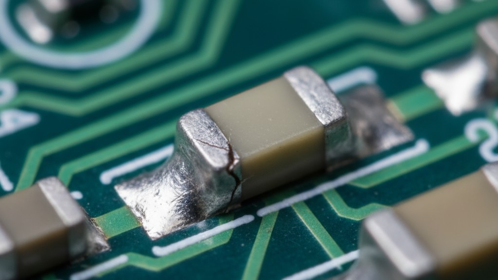
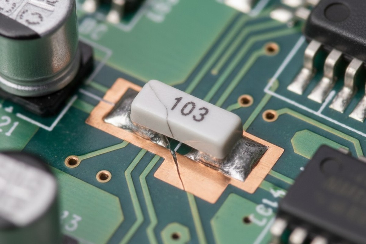
Vibration failures originate from a simple mechanical reality: a populated PCB is a multi-mass system with distinct resonance frequencies. When external vibration excites a resonance mode, the board flexes. Components mounted to that board, particularly heavy ones like transformers or large capacitors, do not flex at the same rate. The solder joints become the flexural hinge, experiencing cyclic stress with each oscillation. This isn’t a high-stress event in any single cycle. It is a low-cycle fatigue process where microcracks initiate at the solder fillet and propagate with each vibration cycle until the electrical connection fails.
The damage is insidious because it is not visible. A solder joint can lose fifty percent of its cross-sectional area to internal cracking and still appear intact under a microscope. The failure manifests as an intermittent open circuit under vibration—a maddening fault to diagnose. The crack propagation rate depends on stress amplitude, which is itself a function of how close the excitation frequency is to a board resonance. A board with a first-mode resonance at 180 Hz will accumulate damage far faster in a vehicle engine compartment, where vibration energy is concentrated, than an identical board in a fan-cooled enclosure.
Components with high mass and small footprints are the most vulnerable. A through-hole capacitor with long, rigid leads acts as a cantilever beam, concentrating stress at the solder fillet. A large surface-mount inductor near a board edge will drive flexure that surrounding smaller components do not experience. The failure is not random; it is deterministic, governed by mass distribution, board stiffness, and the excitation spectrum. Ruggedization addresses this by either damping the resonance or stiffening the joint through encapsulation, both of which reduce the cyclic stress.
Thermal Expansion Mismatch and Component Cracking
Thermal cycling induces failure through a different mechanism: cracks at material interfaces. Every material in a PCBA has a coefficient of thermal expansion (CTE). FR4 laminate expands differently than copper, which expands differently than a component’s ceramic package, which expands differently than the silicon die inside. As the assembly heats and cools, each material expands or contracts at its own rate, creating shear stress at the interfaces. Over thousands of cycles, this stress accumulates as delamination, solder joint cracking, or die-attach failures inside components.
The CTE mismatch between the PCB and its components is the primary driver. A typical FR4 board has a CTE of 14-17 ppm/°C, while a ceramic component might be 6-7 ppm/°C. Across a 100°C thermal swing, a 20 mm component will experience a differential expansion of roughly 20-30 microns relative to the board. That displacement is absorbed by the solder joints. If the joint is rigid, stress is high and fatigue life is short. This is why lead-free solder, with its higher modulus and lower ductility, has a shorter thermal fatigue life than traditional tin-lead; it cannot yield as easily, so the stress per cycle is higher.
Failure often starts at the corner solder joints of large components, where displacement is greatest. Ball grid arrays are particularly susceptible because the solder balls are short and stiff, offering little compliance. The crack propagates through the solder until electrical continuity is lost, again remaining invisible until failure. Encapsulation can mitigate this by coupling the component to the board, reducing relative displacement. A potting compound with a low modulus and a CTE close to the board’s will absorb some of the stress. A rigid epoxy with a high CTE can make the problem worse. This is why chemistry selection is a primary engineering decision.
The Three Core Protection Strategies
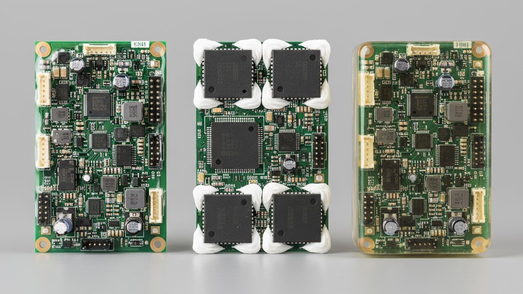
Ruggedization methods exist on a spectrum defined by the degree of environmental isolation they provide and the rework difficulty they impose. At one end, conformal coating offers a thin moisture barrier with minimal mechanical reinforcement. At the other, full potting encases the entire assembly in a solid block of polymer, providing maximum protection at the cost of any rework capability. Selective staking occupies the middle ground. Each method serves a distinct purpose, and each is only as effective as the chemistry chosen to implement it.
Conformal Coating for Surface-Level Defense
Conformal coating is a thin polymer layer, typically 25 to 125 microns, applied to the surface of a populated PCB. Its primary function is environmental protection. It provides a dielectric barrier against moisture, a physical barrier against dust, and limited chemical resistance. The coating conforms to the board’s topography, covering components and traces without filling the spaces between them. This minimizes added weight and allows for visual inspection, albeit through a translucent film. The mechanical reinforcement from a conformal coat is minimal; it is not a structural solution for vibration or thermal stress.
The value of conformal coating lies in its simplicity and reversibility. It can be applied by spray, brush, or robotic dispensing, and removed with solvents or mechanical abrasion for rework. This makes it the default choice for assemblies facing moisture or contamination risks without significant mechanical stress. It is also the only ruggedization method that doesn’t obstruct access to test points or connectors, assuming they are masked during application. The limitation is that the protection is only surface-level. If there is a void under a component, the coating will bridge over it but not fill it.
Staking for Targeted Reinforcement
Staking is the application of a structural adhesive to specific, high-risk components. The adhesive forms a fillet between the component body and the PCB, coupling the two and increasing the joint’s stiffness. This reduces the flexural displacement the solder joints experience under vibration, lowering the cyclic stress and extending fatigue life. Staking doesn’t provide environmental sealing, but it can be combined with a conformal coat to address both mechanical and environmental threats.
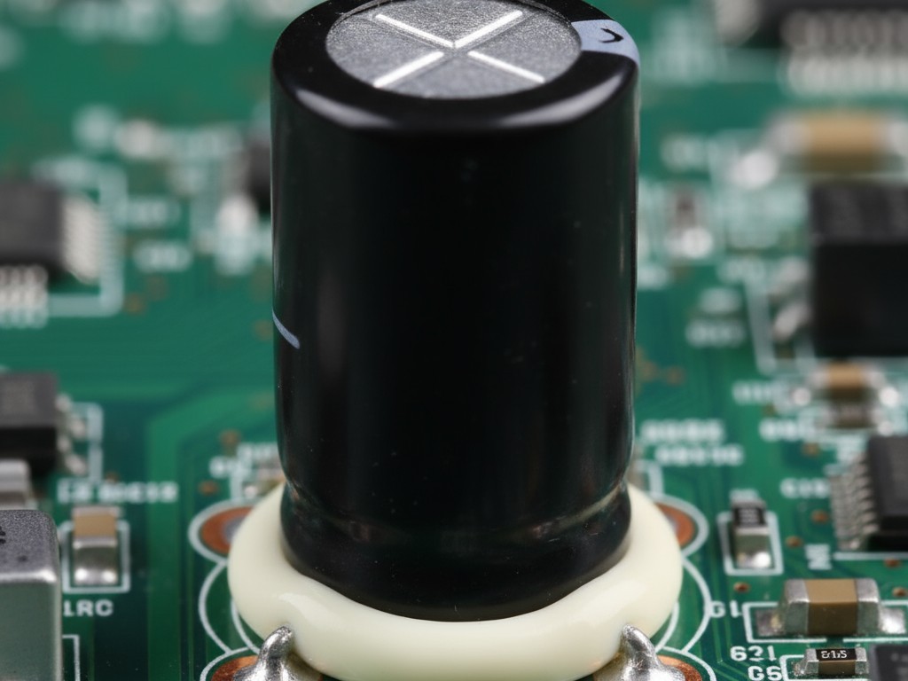
The advantage of staking is its selectivity. Only components that need reinforcement receive it, minimizing material cost and preserving rework access to the rest of the board. A large capacitor might be staked, while the surrounding logic is left untreated. The disadvantage is that staking requires process discipline. The adhesive must be applied with the correct volume in the correct location. Too little material is ineffective; too much can wick under the component, creating a rigid bond that induces stress rather than relieving it. Staking is the method of choice when vibration is the dominant threat and the failure mode is predictable. It is a mechanical fix, not an environmental one.
Potting for Maximum Environmental Isolation
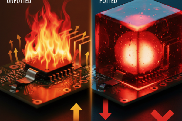
Potting encapsulates an entire assembly in a solid mass of polymer. The board is placed in a housing, and liquid encapsulant is poured in until the components are submerged. After curing, the assembly is a single, solid block. Potting provides the highest level of protection against moisture, chemicals, impact, and abrasion. It also offers the most mechanical damping and stress distribution. A potted assembly has no accessible resonance modes in the audio frequency range, and the encapsulant distributes thermal expansion stress across a much larger volume.
The trade-off is rework. A potted assembly is permanent. Removing the encapsulant is destructive, requiring mechanical milling or harsh chemicals that risk damaging the board. Potting is justified only when the environmental threat is severe—submersion, chemical exposure, extreme thermal cycling—or when the assembly is truly disposable. The effectiveness of potting is almost entirely determined by the choice of encapsulant. The wrong choice doesn’t just fail to protect—it actively induces failure, which is why chemistry is not a secondary consideration.
Chemistry Fundamentals: Urethane, Epoxy, and Silicone
Urethane, epoxy, and silicone are not simply variants of one another. They are distinct polymer families with fundamentally different mechanical properties, thermal behavior, and cure mechanisms. The choice among them is the highest-leverage decision in ruggedization, determining how the encapsulant responds to stress, couples to the assembly, and behaves over time. Datasheets provide metrics, but field experience reveals the full story.
| Property | Urethane | Epoxy | Silicone |
|---|---|---|---|
| Shore Hardness Range | 30A – 75D | 60D – 85D | 10A – 60A |
| Tensile Modulus | Medium (500-2k MPa) | High (2k-4k MPa) | Low (1-10 MPa) |
| CTE (ppm/°C) | 80-150 | 50-80 | 200-300 |
| Service Temp Range | -40°C to 120°C | -40°C to 150°C | -60°C to 200°C |
| Rework Difficulty | Moderate | Very High | Low to Moderate |
Urethane Chemistries and Flexibility Trade-offs
Urethane encapsulants are two-part systems that form a polymer with both hard and soft segments, giving them a characteristic blend of flexibility and toughness. A urethane can be formulated to be soft and elastomeric like a silicone, or hard and rigid like an epoxy. This tunability makes urethane the most versatile chemistry, but it also makes specification critical. A urethane chosen for flexibility might have a CTE far higher than the PCB, creating thermal stress instead of relieving it.
The optimal formulation depends on the primary threat. For vibration-dominated environments, a harder urethane with moderate flexibility provides both damping and joint reinforcement. For thermal cycling, a softer urethane with a CTE closer to the board’s minimizes differential expansion stress. Urethanes are sensitive to moisture during their exothermic cure, and pot life is limited once mixed. These constraints require process control, but they are not prohibitive. What makes urethane the workhorse of ruggedization is its proven track record in automotive and industrial applications where both thermal and mechanical stress are present.
Epoxy Resins and Structural Rigidity
Epoxy encapsulants are thermosetting polymers that form a highly cross-linked network, giving them exceptional rigidity and mechanical strength. An epoxy potting compound is, in effect, a structural adhesive. It bonds aggressively, provides excellent dimensional stability, and resists a wide range of chemicals. For applications where the encapsulant must also serve as a mechanical support, epoxy is the default choice. This rigidity is both its strength and its weakness.
A rigid epoxy does not accommodate differential thermal expansion. If the epoxy’s CTE is significantly different from the PCB’s, every thermal cycle induces stress at the interface. Over time, this stress can cause delamination or cracking. It can also be transmitted to solder joints, reducing fatigue life instead of extending it. This is a common failure mode in epoxy-potted assemblies and the reason epoxy is not a universal solution. The rework problem with epoxy is also severe. A fully cured epoxy is nearly impossible to remove without destroying the board, making it a permanent commitment suitable only for disposable assemblies.
Silicone Materials and Thermal Performance
Silicone encapsulants are based on polydimethylsiloxane polymers, resulting in a highly flexible material with a very low modulus and excellent thermal stability. Silicones retain their properties across a wider temperature range than urethanes or epoxies, from cryogenic levels to over 200°C. They are also highly resistant to UV exposure and oxidation. When thermal extremes are the dominant stress, silicone is often the only chemistry that will survive.
The low modulus is silicone’s defining characteristic. It deforms easily and provides essentially no structural reinforcement. If vibration is the primary threat, silicone alone will not prevent it. Its advantage is thermal stress relief. The combination of low modulus and high elongation allows silicone to accommodate differential expansion without transmitting stress to solder joints. This makes silicone the chemistry of choice for assemblies that undergo extreme or rapid thermal cycling. Rework is also straightforward; the cured material can be peeled or cut away. The trade-off is that silicone provides no mechanical support and limited environmental sealing compared to a hard potting compound. It is a thermal solution, not a mechanical one.
Matching Protection Method to Application Requirements
The decision matrix for ruggedization is unforgiving. It starts with an honest assessment of the actual environmental threats, not a worst-case combination of every possibility. An assembly in an automotive engine compartment faces sustained vibration, moderate thermal cycling, and oil mist. An outdoor control panel sees wide thermal cycling and moisture but minimal vibration. These are different threat profiles requiring different solutions.
For vibration-dominated environments, the goal is to reduce solder joint stress. Conformal coating is insufficient. Selective staking of high-mass components with a medium-hardness urethane is the most targeted solution. If the vibration is broad or complex, potting with a harder urethane couples the entire assembly into a single structure.
For thermal cycling environments, the goal is to minimize differential expansion stress. Silicone potting is the most effective solution for wide thermal swings. Its low modulus accommodates expansion without transmitting stress. If some mechanical reinforcement is also needed, a soft urethane is a good compromise. Epoxy should be avoided unless the CTE is carefully matched and the thermal excursion is small.
When both vibration and thermal cycling are present, the solution must address both threats. A common mistake is selecting a hard epoxy for vibration, which then fails under thermal cycling. The correct approach is often a medium-hardness urethane formulated for both flexibility and support.
Skipping ruggedization entirely is also a valid decision. If the assembly will operate in a benign, temperature-controlled environment, the cost and rework penalty of encapsulation is not justified. Over-specification is its own failure mode.
The Case Against Exotic Encapsulants
Exotic encapsulants appear on datasheets with impressive metrics, but these advantages are narrow. The real question is whether a performance gain in one metric justifies the risks to supply chain stability, process complexity, and field repairability. In most cases, the answer is no.
The primary risk is limited field history. A urethane formulation in production for 15 years has known failure modes and a documented degradation behavior. An exotic material introduced three years ago does not. Its accelerated aging tests are models, not evidence. When an unanticipated failure occurs in year five, there is no backup supplier and no knowledge base to guide the analysis.
The process complexity of exotic materials is also often underestimated. A UV-cure system requires line-of-sight access to all surfaces, and any shadowed region will remain uncured. Moisture-sensitive materials require environmental controls that may not fit existing workflows. Finally, rework is often impossible. If a component fails in the field, the entire assembly is scrap. This is unacceptable for high-value industrial or medical equipment. For these reasons, we favor proven, commercial-grade chemistries over MIL-spec designations or exotic formulations. A commercial urethane from a reputable supplier, with a documented history in similar applications, will often outperform a material chosen simply for passing a generalized test protocol.
In-House Vibration Screening as the Validation Step
Ruggedization is a hypothesis about how an assembly will respond to stress. Vibration screening is the experiment that tests that hypothesis before a product reaches the field. These tests are not pass-fail certifications; they are diagnostic tools that provide data to guide material selection and design changes. Performing these tests in-house is the difference between fixing a problem with engineering time and fixing it with a product recall.
Swept-Sine Testing for Resonance Identification
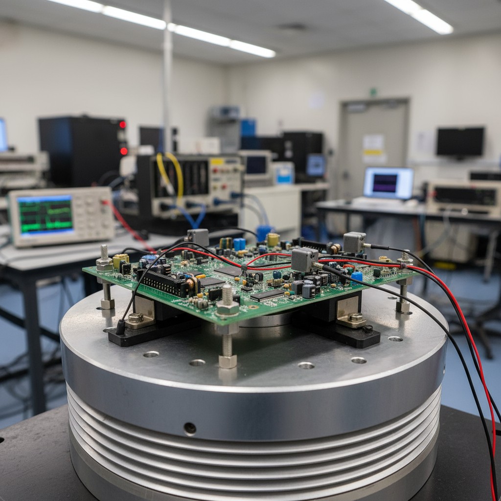
A swept-sine test applies a single-frequency sinusoidal vibration to the assembly, slowly sweeping from a low frequency (e.g., 20 Hz) to a high one (e.g., 2000 Hz). Accelerometers measure the response. When the excitation frequency matches a resonance frequency, the response amplitude increases dramatically. This amplification factor, which can be 10x or higher, precisely identifies where the assembly is most vulnerable and which components experience the most stress. That data drives the ruggedization strategy. Without it, the decision is a guess.
Random Vibration Profiles for Real-World Simulation
Random vibration testing applies a multi-frequency excitation that more closely approximates a real-world service environment. The input is a broadband signal defined by a power spectral density profile, which specifies the vibration energy at each frequency. The test duration can be extended for hours to accumulate fatigue damage equivalent to years of field exposure. It is the closest approximation to real-world vibration achievable in a lab and the validation test that must be passed before production. The test is destructive by design. The goal is to accumulate enough vibration dose to either induce a failure or demonstrate survival with margin. An assembly either survives the profile or it does not.
Cure Profiles and Production Realities
The choice of encapsulant chemistry dictates production throughput. Cure time is the interval between dispensing the material and being able to handle the assembly. A room-temperature cure might take 24 hours; a heat-accelerated cure, 30 minutes; a UV cure, 10 seconds. These are not just cycle time differences; they represent fundamentally different production workflows.
Thermal cure systems can be accelerated with heat, but if the encapsulant mass is large, the exothermic heat of reaction can add to the external heat, potentially damaging sensitive components. The cure schedule must account for both external temperature and expected exotherm.
UV-cure systems eliminate the wait time but introduce line-of-sight constraints. Any area shadowed by a component will not cure, making UV cure suitable for conformal coatings on flat boards but problematic for potting complex assemblies.
Vapor phase deposition, typically for conformal coatings, offers uniform coverage on complex geometries but is a slower batch process. For most applications, selective robotic spray or dispensing provides adequate coverage with better throughput. The choice depends on the geometry of the board and the criticality of complete coverage.
