PCB photoplotting is an electro-mechanical-optical process that reveals a latent image in a medium, usually a high-contrast monochromatic (black-and-white) photographic picture, using a light source under computer control. After the exposure step is complete, the medium is processed in a photo processor using a developer solution, along with fixing, washing, and drying.
Applications of PCB Photoplotting
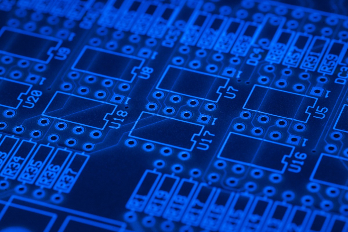
Just about any conceivable image can be formed. PCB photoplotters are primarily used for the production of PCBs (printed circuit boards) and IC packaging. Other application areas include chemical milling and specialized graphic arts. Photoplotting is the first step in making photolithography masks for printed circuit boards. In the PCB industry, these masks are called PCB photoplots and are generally limited to features of 20 µm or more. Integrated circuits are made in a similar fashion using photomasks with sub-micrometer feature sizes; photomasks are traditionally produced by photoreducing photoplotter output.
Historical Background
The first photoplotter was introduced by Gerber Scientific Inc. (now Ucamco) in the 1960s. Early machines used a xenon high-intensity discharge (HID) flash lamp and required an image mounted on a rotating aperture wheel onto the photosensitive surface of the film or glass plate. The imaging head assembly traversed over the surface of the medium without touching it to produce draws and flashes. Draws are vectors or arcs created by continuous illumination as the imaging head moves over the photosensitive surface. The flashes create single simple graphics by shining light through an aperture of the appropriate shape at a fixed location.
Modern Photoplotting Techniques
Raster-Scan Equipment
Modern photoplotters are generally raster-scan machines that use a laser beam focused to one or more spots and modulated at multi-megahertz rates to form the image. Initially, green argon-ion lasers and blue helium-cadmium lasers were frequently used. Current models utilize red helium-neon lasers, red laser diodes, or even red LEDs (light-emitting diodes).
Photoplotters vs. Imagesetters
Photoplotters are closely related to imagesetters. Photoplotters differ from their imagesetting counterparts in the type of controller used to produce the image, and in the resolution and absolute accuracy of the image, with photoplotters meeting much more stringent specifications than imagesetters.
Laser Direct Imaging (LDI)
The most recent development related to photoplotting is LDI (Laser Direct Imaging), which utilizes a high-power laser or Xenon lamp to directly expose photoresist on a coated substrate instead of exposing photographic film. This eliminates the handling of photographic film. LDI machines currently sell for prices in the half-million U.S. dollar range.
Input Formats
The input of photoplotters is a vector graphics file, usually in Gerber File Format. Some photoplotters also accept bitmap formats such as TIFF.
Conclusion
PCB photoplotting has evolved significantly since its inception in the 1960s. From the early use of xenon HID flash lamps to the modern adoption of laser direct imaging, the technology continues to advance, offering higher precision and efficiency. As the industry moves forward, the applications and capabilities of photoplotting are likely to expand, further solidifying its role in the production of printed circuit boards and other specialized graphic arts.


